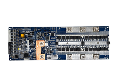

The adapter board is an interface converter that can convert the signal of one interface to the signal of another interface, so that incompatible devices can communicate and interact.
The indicator board integrates indicator lights on the main board, and expresses different information by flashing different light languages.
The adapter board usually includes multiple slots and corresponding pins for inserting different types of plugs or cables to realize data transmission, signal conversion and power supply between different devices. Due to its small size, it is convenient to use, install and maintain in some special scenarios.
The indicator board has lamp posts and lamp beads of different sizes and lengths for different scenarios. At the same time, additional accessories such as communication interfaces, switches, etc. can be integrated on the indicator board.
When the motherboard has been finalized and stabilized, functions can be added through the adapter board;
Compared with customized development of the motherboard, customized adapter boards are cheaper and easier;
Small size, easy to maintain and install
Adapter boards are interface expansion components used to connect a battery management system with external devices, cables, switches, indicators, or communication modules. When two components use different connector layouts, pin definitions, or signal interfaces, an adapter board can provide the electrical and physical transition required for data transmission, signal conversion, or power distribution. In a BMS application, the board may be installed between the main control board and an external device without requiring a complete redesign of the BMS motherboard. This makes it easier to add communication interfaces, LED indicators, switches, or project-specific connectors after the core BMS design has been finalized. A suitable board adapter must match the voltage level, signal type, connector specification, pin assignment, current requirement, and communication method of the connected devices. It should be treated as an engineered BMS component rather than as a universal plug converter.
A board adapter creates a controlled connection between the BMS motherboard and components that use different interfaces or wiring configurations. The board receives signals through one connector and routes, converts, or redistributes them through another connector according to the required pin definition. Depending on the design, adapter boards may support data communication, status signals, control switches, indicator outputs, or low-power supply connections. This approach allows a stable BMS motherboard to communicate with different displays, indicator boards, wiring harnesses, or external devices without changing the main circuit design for every project. However, an adapter board does not automatically make all interfaces compatible. The communication protocol, signal voltage, connector type, pin sequence, power requirements, and grounding method must still be matched correctly. For customized battery projects, buyers should provide interface drawings, cable definitions, communication requirements, and connected-device specifications before the adapter board design is confirmed.
Although adapter boards and indicator boards may be listed within the same BMS accessory category, they perform different primary functions. An adapter board is mainly used for interface conversion, signal routing, connector expansion, or communication between devices that cannot be connected directly. An indicator board is mainly designed to display BMS or battery operating information through LEDs, switches, or other visible status components. Different LED colors, positions, or flashing patterns can represent power status, charging, communication, alarms, or other system conditions defined by the BMS logic. Some products may combine both functions by integrating indicator lights, communication ports, switches, and interface conversion on one board. Therefore, buyers should not select a board adapter or indicator board based only on its physical appearance. The correct choice depends on whether the project needs signal conversion, status indication, additional controls, connector adaptation, or a customized combination of these functions.
Selecting adapter boards begins with identifying the devices that must be connected and the exact function the board must perform. Buyers should confirm the BMS model, connector type, pin definition, signal voltage, current requirement, communication protocol, cable length, and installation space. It is also important to determine whether the board needs interface conversion, signal routing, LED indication, switches, power distribution, or communication expansion. If the board adapter will connect to a display, inverter, indicator board, or external controller, the signal direction and communication mapping must be checked on both sides. Environmental conditions such as temperature, vibration, moisture, and enclosure limitations may also affect the PCB layout and connector selection. For customized development, the supplier should receive the BMS interface drawing, connected-device specification, wiring diagram, functional requirements, and expected production quantity. Complete project information helps prevent pin conflicts, incompatible signals, and unnecessary motherboard modifications.