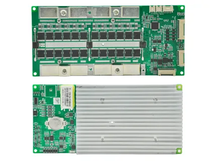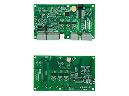
For a typical 12V LiFePO4 battery pack, choose a 4S LiFePO4 BMS that matches the battery chemistry, cell configuration, maximum continuous charge/discharge current, peak load, temperature requirements, and communication needs.
Do not select a 12V BMS simply according to battery capacity. A 12V 100Ah battery does not automatically require a 100A BMS. The correct current rating depends primarily on the load, charger, inverter, motor, and the current capability of the cells.
For most 12V LiFePO4 applications, check these six specifications first:
Battery chemistry: LiFePO4
Series configuration: 4S
Continuous discharge current: higher than the maximum continuous load
Peak current: sufficient for inverter or motor startup
Maximum charging current: compatible with the charger, alternator, or solar controller
Protection and communication: temperature sensing, balancing, CAN, RS485, Bluetooth, etc., as required
A standard 12V LiFePO4 battery has four 3.2V cells or four parallel cell groups connected in series, giving a nominal pack voltage of 12.8V. Therefore, it normally requires a 4S LiFePO4 BMS.
The BMS must also use protection parameters designed for LiFePO4 chemistry.
This matters because “12V lithium battery” can describe several different battery configurations. A conventional lithium-ion chemistry such as NMC may use a different number of cells in series and different overvoltage and undervoltage limits. A 12V Li-ion BMS therefore should not be treated as automatically interchangeable with a 4S LiFePO4 BMS.
| Battery Type | Typical Configuration | Nominal Pack Voltage | BMS Requirement |
|---|---|---|---|
| LiFePO4 | 4S | 12.8V | 4S LiFePO4 BMS |
| NMC/NCA Li-ion | Often 3S | 10.8–11.1V | BMS matched to NMC/NCA and cell count |
| Lead-acid | 6 cells | ~12V | Does not use a lithium BMS |
When choosing a BMS for a 12V battery, always confirm chemistry and series count before considering current rating or communication functions.
A 12V LiFePO4 BMS normally monitors four series-connected cell groups (4S).
For example:
4 × 3.2V = 12.8V nominal
4 × 3.65V = 14.6V at the typical upper cell-voltage limit
Adding cells in parallel increases battery capacity, but it does not change the required series count. A 4S1P, 4S2P, or 4S10P LiFePO4 pack is still a 4S system from the BMS voltage-monitoring perspective.
This is why battery capacity and BMS series configuration must be considered separately.
The BMS should be sized according to maximum current, not Ah capacity alone.
A 12V 100Ah battery may work with a 50A, 100A, 150A, or 200A BMS depending on the application and cell specifications.
For an inverter system, estimate current using:
Battery Current ≈ Load Power ÷ Battery Voltage ÷ Inverter Efficiency
Assuming approximately 12V under load and 90% inverter efficiency:
| AC Load | Approx. Battery Current |
|---|---|
| 500W | 46A |
| 1,000W | 93A |
| 1,500W | 139A |
| 2,000W | 185A |
The BMS should not be designed to operate continuously at its absolute current limit. Appropriate current margin should be included based on thermal conditions, wiring, cell capability, enclosure design, and expected duty cycle.
Peak current is equally important. Motors, compressors, pumps, and inverters can draw substantially more current during startup. A BMS that handles the normal operating current but trips whenever the inverter starts is undersized for the application. Industry sizing guidance therefore commonly considers both continuous load and surge current.
No.
100Ah describes battery capacity; 100A describes current. They are different electrical parameters.
Consider two 12V 100Ah batteries:
Battery A supplies a 30A DC load.
Battery B powers a large inverter drawing 120A.
They have the same Ah capacity, but their BMS current requirements are very different.
BMS selection must also remain within the discharge-current capability specified by the cell manufacturer. Installing a 200A 12V battery BMS does not make cells rated for 100A continuous discharge capable of safely delivering 200A.
The complete current path—including cells, busbars, BMS MOSFETs, cables, connectors, terminals, and fuses—must be engineered for the required current.
The maximum charge-current rating of the BMS must be at least as high as the maximum current the battery can receive from its charging sources.
Check all possible sources, including:
AC battery chargers
Solar MPPT controllers
DC-DC chargers
Vehicle alternators
Regenerative charging systems
For example, if a solar controller can provide 50A and an additional charger can operate at the same time, the design should consider the maximum possible combined charging current rather than evaluating each charger separately.
The charger should control normal charging behavior. BMS overvoltage protection is a safety layer, not a substitute for a correctly configured LiFePO4 charger.
Only if the BMS explicitly supports the LiFePO4 chemistry, correct series count, and appropriate protection parameters.
The term 12V Li-ion BMS can be misleading because lithium-ion is a broad category. NMC, NCA, LiFePO4, and other lithium chemistries do not necessarily use the same nominal cell voltage or protection thresholds.
Using a BMS with incorrect voltage thresholds can cause premature protection trips, incomplete charging, excessive discharge, or inadequate cell protection.
For a 12.8V LiFePO4 pack, the safest specification is a 4S BMS specifically configured or configurable for LiFePO4.
A professional 12V BMS should provide more than simple overcharge protection.
At minimum, evaluate:
Cell overvoltage and undervoltage protection
The BMS should monitor individual cell groups rather than relying only on total pack voltage.
Charge and discharge overcurrent protection
Separate thresholds help protect the battery during abnormal charger or load conditions.
Short-circuit protection
Fast detection is essential for high-current 12V systems.
Temperature monitoring
The BMS should monitor battery and/or power-device temperatures and apply charge or discharge protection according to cell specifications.
Cell balancing
Balancing helps prevent individual cell voltages from drifting apart over repeated cycles.
SOC/SOH monitoring
For energy storage, backup power, and intelligent battery systems, accurate state-of-charge and battery-health data can improve system management.
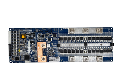
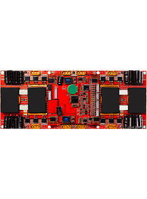
ENJIE's 12V battery management platform, for example, monitors individual cell voltage, pack voltage, charge/discharge current and multiple temperature points while providing overvoltage, undervoltage, overcurrent, temperature, short-circuit and balancing functions.
A standard BMS can be sufficient when the battery only requires local protection and balancing.
A smart BMS becomes more valuable when the battery must communicate with an inverter, energy storage controller, vehicle controller, monitoring platform, or multiple battery modules.
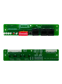
Depending on the system, useful interfaces include:
CAN
RS485
Bluetooth
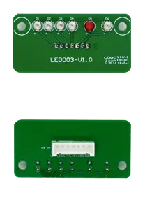
LCD/display interfaces
Parallel battery communication
Remote parameter configuration
For OEM energy-storage and lead-acid replacement applications, communication compatibility is often just as important as the current rating.
For example, ENJIE's EMU1204 is designed for 4S battery applications and supports CAN/RS485 communication, balancing and high-current operation for applications including energy storage and lead-acid-to-lithium replacement.
Before ordering a BMS for a 12V battery, confirm:
Chemistry: LiFePO4, NMC, LTO, or another chemistry?
Series count: Is the pack actually 4S?
Continuous load: What is the highest sustained battery current?
Peak load: What happens when the inverter or motor starts?
Charging current: What is the maximum combined charger input?
Cell limits: Can the cells safely deliver the required current?
Temperature requirements: Is low/high-temperature protection required?
Balancing: Is passive balancing sufficient for the pack design?
Communication: Does the application need CAN, RS485, Bluetooth, or display support?
System architecture: Will batteries operate independently, in parallel, or in series?
For commercial battery projects, also evaluate BMS reliability, parameter customization, firmware support, communication protocol integration, production consistency, and technical support—not simply price per board.
Choosing the right 12V BMS starts with the battery architecture rather than the current label printed on the BMS.
For most 12V LiFePO4 batteries, a 4S LiFePO4 BMS is required. From there, select the current rating according to the real continuous and peak load, verify the maximum charging current, match the BMS protection thresholds to the cells, and determine whether the application requires balancing, temperature management, CAN/RS485 communication, or multi-battery operation.
For OEM battery manufacturers, energy-storage integrators, and lead-acid-to-lithium conversion projects, ENJIE provides 4S 12V BMS solutions with standard and smart configurations for different current and communication requirements. ENJIE's current 12V portfolio includes options in the 100A–200A range for lead-acid replacement and ESS applications.
For LiFePO4 chemistry, a 4S pack has a nominal voltage of 12.8V and is commonly referred to as a 12V battery system.
It depends on the load. A 100A BMS may be suitable when continuous and peak currents remain within its specifications, but a high-power inverter or motor may require a higher-current BMS. Battery Ah capacity alone cannot determine BMS amperage.
Potentially, but only if the cells, busbars, cables, connectors, terminals, and other components are capable of handling the required current. A higher-rated BMS does not increase the safe current capability of the cells.
A rechargeable multi-cell LiFePO4 battery pack should have an appropriate battery management and protection system to monitor individual cell conditions and protect against abnormal voltage, current, temperature, and short-circuit conditions.