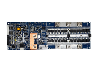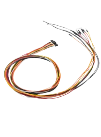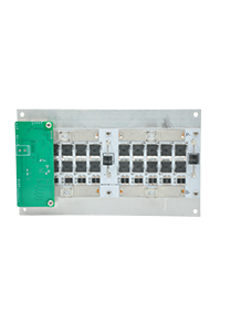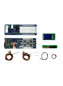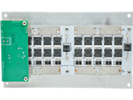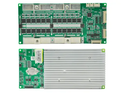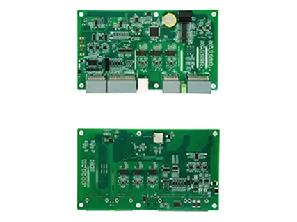
For most 48V-class LiFePO4 energy storage systems, the correct choice is a 16S LiFePO4 48V BMS designed for a 51.2V nominal battery pack. Beyond cell count, the BMS must support the system's real continuous current, inverter surge current, charging current, temperature range, balancing requirements, communication protocol, and parallel battery architecture.
For a typical residential ESS, BMS selection should begin with four questions:
Is the battery definitely 16S LiFePO4?
What is the inverter's maximum DC current demand?
Does the BMS communicate correctly with the inverter through CAN or RS485?
Will multiple battery packs operate in parallel?
Getting these parameters right is more important than simply choosing the highest current rating available.
A standard 48V-class LiFePO4 battery normally uses 16 cells in series:
16 × 3.2V = 51.2V nominal
Therefore, most residential solar and energy storage batteries marketed as "48V LiFePO4" require a 16S BMS.
Do not select the BMS according to the "48V" label alone. Battery chemistry and actual series count must be verified first.
For example:
| Battery Chemistry | Typical Configuration | Nominal Voltage | Typical BMS |
|---|---|---|---|
| LiFePO4 | 16S | 51.2V | 16S LiFePO4 BMS |
| NMC Li-ion | 13S | ~48V | 13S NMC BMS |
This distinction is especially important when sourcing a lithium ion battery BMS 48V, because different lithium chemistries use different cell voltages and protection thresholds.
The BMS current rating should be determined primarily by inverter power and maximum battery current, not battery capacity in Ah.
A useful calculation is:
Battery Current ≈ Inverter Power ÷ Battery Voltage ÷ Inverter Efficiency
For example, with a 5kW inverter, a 51.2V battery, and approximately 92% inverter efficiency:
5,000 ÷ 51.2 ÷ 0.92 ≈ 106A
A 100A BMS would be operating too close to its limit in this situation. A 150A BMS provides more appropriate operating margin, assuming the cells, cables, busbars, terminals, and other pack components are also designed for that current.
Typical reference values are:
| Inverter Power | Approx. DC Current at 51.2V* | Practical BMS Range |
|---|---|---|
| 3kW | ~64A | 75A–100A |
| 5kW | ~106A | 150A |
| 8kW | ~170A | 200A or system-specific design |
*Approximate values assuming 92% inverter efficiency.
Continuous current should not be confused with peak current. Compressors, pumps, motors, and some inverters can create short-duration surge loads. The BMS overcurrent strategy must tolerate legitimate startup demand while still protecting the battery from actual faults.
It depends on the power demand.
A 51.2V 100Ah battery stores approximately 5.12kWh, but the 100Ah capacity does not mean it automatically requires a 100A BMS.
For example, the same 100Ah battery may be used with:
A 3kW inverter drawing around 60–70A
A 5kW inverter drawing more than 100A at high load
Multiple parallel batteries sharing inverter current
The correct BMS battery 48V current rating must therefore be based on the actual charge/discharge current and cell specifications.
A 200A BMS also does not turn a battery using 100A-rated cells into a 200A battery. The permitted current is limited by the weakest component in the complete current path.
In energy storage applications, communication compatibility is often just as important as voltage and current.
A smart 48V BMS can send information such as:
State of charge
Battery voltage
Charge and discharge limits
Temperature
Alarm and protection status
Available charging/discharging current
to the inverter or PCS.
CAN and RS485 are commonly used in residential ESS. When the BMS and inverter communicate correctly, the inverter can adjust charging and discharging according to real-time battery conditions instead of depending only on fixed voltage settings.
This becomes particularly important in OEM battery projects because different inverter manufacturers use different communication protocols.
ENJIE's 48V ESS BMS platform supports CAN/RS485 communication and compatibility with more than 40 inverter protocols on selected models, helping battery manufacturers integrate with a wider range of ESS platforms.
Yes. Parallel battery systems require more than simply connecting multiple battery packs to the same DC bus.
The design should consider:
Current sharing between battery modules
SOC differences between packs
Connection inrush current
Parallel communication
Automatic address assignment
Charge/discharge current limiting
Failure isolation
Differences between new and aged batteries
Without proper management, one battery may carry significantly more current than another, especially when pack voltage, SOC, internal resistance, or cable resistance differs.
For expandable residential ESS, choose a 48V BMS designed specifically for multi-pack parallel operation rather than assuming any standalone BMS can be scaled safely.
ENJIE's 48V BMS platform is designed for expandable energy storage applications and supports more than 20 units in parallel in applicable configurations.
For energy storage, evaluate the protection architecture rather than looking only at the advertised amp rating.
A professional BMS should include:
Cell overvoltage and undervoltage protection
Individual cell monitoring is essential because total pack voltage can appear normal while one cell has already reached an unsafe limit.
Charge and discharge overcurrent protection
Protection settings should match the cell capability, inverter behavior, and expected operating load.
Short-circuit protection
Short-circuit response must be distinguished from normal short-duration inverter surge current.
Temperature protection
The BMS should monitor cell and power-stage temperatures and restrict charging or discharging when necessary.
Cell balancing
Balancing helps control voltage deviation between cells, particularly near the upper SOC range.
Current limiting
This is valuable in parallel ESS architectures because it can reduce excessive equalization or charging current between battery modules.
Neither is automatically better for every battery.
Passive balancing is widely used in well-matched LiFePO4 energy storage packs because it is simple, reliable, and cost-effective. If cells are properly selected and the battery operates normally, passive balancing can be sufficient.
Active balancing becomes more useful when:
Battery capacity is large
Cell mismatch is more significant
Faster balancing is required
The system experiences wider SOC variation
Long-term module consistency is particularly important
However, a high balancing current cannot compensate for poor cell matching or a fundamentally defective cell.
For commercial battery pack production, cell consistency remains the first line of control.
Before finalizing a 48V BMS for a LiFePO4 energy storage project, confirm:
Chemistry and series count — typically 16S/51.2V for 48V-class LiFePO4 ESS.
Continuous discharge current — based on maximum inverter load.
Peak current and duration — especially for motor and inverter startup.
Maximum charge current — including solar, grid charger, or other simultaneous charging sources.
Cell current capability — the BMS rating must not exceed what the battery design can safely deliver.
CAN/RS485 compatibility — verify the exact inverter protocol, not only the physical interface.
Parallel expansion — critical for modular 5kWh, 10kWh, 20kWh, and larger battery systems.
Thermal performance — evaluate current capability under the actual enclosure and ambient temperature.
Balancing strategy — passive or active according to pack requirements.
Configuration and after-sales support — especially important for OEM and customized battery projects.
ENJIE provides 48V BMS solutions covering 50A to 200A for small and medium-sized household energy storage and communication backup applications. Its current product range includes solutions covering up to 16S for mainstream 51.2V LiFePO4 systems, with smart communication and parallel expansion options.
For example, the EMU1101 V16 supports 8S–16S battery configurations and 100A, 150A, and 200A current options, with CAN/RS485 inverter communication and support for more than 40 mainstream inverter protocols.
This type of architecture is particularly suitable for battery manufacturers developing wall-mounted, rack-mounted, and modular residential ESS products where inverter compatibility and scalable battery capacity are key requirements.
Selecting a 48V BMS for a LiFePO4 energy storage system starts with a 16S/51.2V battery architecture, but the final choice depends on much more than voltage.
Current capacity should match the inverter's real continuous and peak demand; communication must match the inverter protocol; and parallel systems require proper current management and module communication. Cell protection, thermal design, balancing, and system expandability should all be evaluated before moving into production.
For OEM battery manufacturers and energy storage integrators, choosing a BMS platform that combines suitable current capacity with broad inverter compatibility and flexible parallel expansion can significantly simplify product development and reduce integration problems.
Most modern 48V-class LiFePO4 energy storage batteries use 16S, producing a nominal voltage of 51.2V. Always verify the actual battery configuration before selecting the BMS.
No. The BMS series count and chemistry must match the battery. A 13S NMC BMS and a 16S LiFePO4 BMS monitor different numbers of cells and use different voltage parameters.
A 5kW inverter can require roughly 100A or more from a 51.2V battery at full load. A 150A BMS is therefore commonly more appropriate than operating a 100A BMS continuously near its maximum rating, provided the cells and pack hardware support that current.
Not every system requires CAN, but CAN or RS485 is strongly recommended when the inverter supports battery communication. It allows the BMS and inverter to coordinate charging, discharging, SOC, and protection limits more effectively.