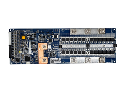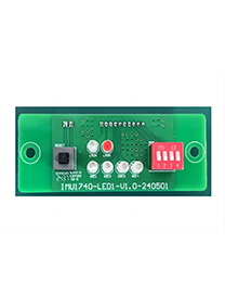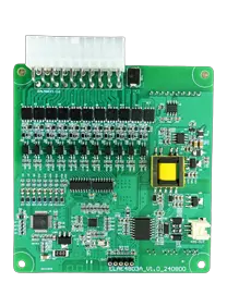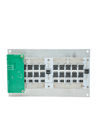
For commercial and industrial energy storage, a high voltage BMS should be selected around the complete battery system—not simply the nominal pack voltage. The critical parameters are the minimum and maximum DC voltage, series cell count, continuous charge/discharge current, BMS architecture, insulation monitoring, contactor and precharge control, PCS/EMS communication, balancing strategy, and system expansion requirements.
For most C&I projects, the BMS should also provide multi-level fault protection and reliable communication between battery modules, battery clusters, the PCS, and the EMS.
A practical selection sequence is:
Battery chemistry and cell configuration → system voltage range → current → BMS architecture → high-voltage protection → communication → balancing/SOC → expansion and certification requirements.
A high voltage battery management system manages a battery string operating at significantly higher DC voltage than typical 12V, 48V, or low-voltage residential battery systems.
In C&I energy storage, these systems commonly use hundreds of volts to match the DC input range of the PCS. ENJIE's current series high-voltage platform, for example, covers 100V–800V systems with 50A, 100A, and 150A configurations.
Unlike a simple low-voltage BMS, an HV BMS generally uses a distributed architecture consisting of:
BMU: Monitors individual cell voltages and temperatures and performs cell balancing.
BCU: Manages battery-cluster SOC, protection logic, communication, and operating status.
High-voltage box: Controls contactors, precharge circuits, current measurement, and high-voltage connection/disconnection.
This architecture allows hundreds of cells to be monitored safely and efficiently.
Do not select the BMS using nominal voltage alone. Calculate the complete operating voltage window.
For a LiFePO4 system:
Maximum system voltage = number of series cells × maximum cell voltage
Minimum system voltage = number of series cells × minimum operating cell voltage
For example, a 192S LiFePO4 battery using a 3.2V nominal cell has:
192 × 3.2V = 614.4V nominal
However, the BMS, contactors, insulation components, connectors, fuses, and PCS interface must be selected according to the actual maximum charging voltage, not only 614.4V nominal.
A common procurement mistake is choosing a BMS high voltage platform whose nominal rating appears sufficient but whose maximum operating or insulation rating leaves inadequate margin at the battery's upper voltage limit.
Current should be calculated from the maximum PCS power and battery operating voltage.
A useful estimate is:
DC Current ≈ PCS Power ÷ DC Bus Voltage ÷ Conversion Efficiency
For a 100kW PCS operating around 600V DC at 95% efficiency:
100,000 ÷ 600 ÷ 0.95 ≈ 175A
This does not automatically mean that a single 175A battery string is required. C&I systems may distribute power across multiple battery clusters.
For example:
| System Design | Approximate Current per Cluster |
|---|---|
| 100kW / 1 × 600V cluster | ~175A |
| 100kW / 2 × 600V clusters | ~88A each |
| 100kW / 4 × 600V clusters | ~44A each |
The final current rating must also consider cell capability, busbars, contactors, fuses, cables, thermal conditions, overload duration, and PCS operating strategy.
Higher BMS current is not automatically better. A well-designed C&I ESS should optimize voltage, current, battery clusters, and PCS power together.
For medium- and high-voltage C&I battery systems, a distributed master-slave architecture is generally more practical than a single centralized board.
A typical two-tier structure uses:
BMU → BCU → PCS/EMS
The BMUs collect cell-level voltage and temperature information. The BCU then evaluates cluster-level SOC, current, voltage, faults, contactor status, and operating limits before communicating with the PCS or EMS.
ENJIE's EHVS500 high-voltage platform uses a two-tier architecture for series-connected battery systems and supports LFP and NCM applications from 100V to 800V.
For larger projects involving multiple independent battery clusters, the system may require another supervisory control layer to coordinate cluster operation.
These are fundamental differences between many low-voltage and high-voltage battery systems.
A high-voltage battery rack must detect deterioration in insulation between the DC bus and chassis or ground.
Poor insulation can create shock hazards, abnormal leakage current, and system faults. The BMS should therefore be able to integrate insulation monitoring into the system protection strategy.
The BMS should control positive and/or negative high-voltage contactors so the battery can be electrically isolated when serious faults occur.
Directly connecting a high-voltage battery to a PCS with large DC-link capacitors can create very high inrush current.
The precharge circuit limits this current before the main contactor closes.
When evaluating a high voltage battery management system, ask the supplier for the actual contactor sequence and fault-handling logic—not simply whether the specification says "precharge supported."
For C&I storage, communication compatibility must be verified at the protocol level, not only at the connector level.
Common interfaces include:
CAN
RS485
Ethernet
Modbus-based communication
The BMS may need to communicate with:
BMUs ↔ BCU ↔ PCS ↔ EMS ↔ monitoring platform
ENJIE's high-voltage BMS platform supports CAN, RS485, and Ethernet communication at the BCU level.
However, having CAN hardware does not mean two devices can communicate automatically. The PCS and BMS must use compatible message definitions, baud rates, IDs, scaling, alarm codes, and charge/discharge control logic.
Before placing an OEM order, provide the BMS supplier with the exact PCS model and communication protocol documentation.
Balancing becomes increasingly important as the number of series cells increases.
If a battery string contains hundreds of cells, relatively small differences in capacity, internal resistance, temperature, or self-discharge can gradually produce larger SOC and voltage differences.
The BMS should therefore:
Monitor every cell independently
Identify maximum and minimum cell voltage
Calculate cell-voltage deviation
Activate balancing according to configurable conditions
Record abnormal cell behavior
ENJIE's current high-voltage BMU specification supports real-time monitoring of multiple cells and temperature points and provides 200mA passive balancing.
For applications requiring stronger imbalance correction, an external active balancing system may also be evaluated according to cell capacity and project requirements.
SOC accuracy has a direct commercial impact because inaccurate SOC estimation can reduce usable battery capacity or cause unexpected charge/discharge limitations.
A professional HV BMS should calculate SOC using more than instantaneous battery voltage, especially for LiFePO4 systems where the voltage curve remains relatively flat across a large portion of the operating range.
When comparing suppliers, ask:
What SOC algorithm is used?
How is SOC calibrated for the selected cell?
How is accumulated current error corrected?
Does SOC compensate for temperature and aging?
How does the algorithm handle power loss and restart?
Is SOH also calculated?
For C&I systems performing peak shaving, demand management, or scheduled charge/discharge, stable SOC estimation is essential for accurate EMS dispatch.
No.
Even when the voltage and current ratings appear compatible, integration can fail because of:
Different CAN or RS485 protocols
Incorrect PCS voltage window
Different charge/discharge limit definitions
Communication timeout behavior
Contactor-control conflicts
Different alarm and fault logic
SOC scaling or data-format differences
PCS compatibility should therefore be validated during system development rather than after the battery cabinet has entered production.
Before choosing a high voltage BMS, confirm the following information with the supplier:
Battery chemistry: LiFePO4, NMC, or another chemistry
Series cell count: total cells per battery cluster
Minimum, nominal, and maximum voltage
Continuous and peak charge/discharge current
Number of battery modules and clusters
BMU and BCU architecture
Insulation monitoring requirements
Contactor and precharge configuration
Cell and temperature sampling requirements
Passive or active balancing strategy
PCS model and communication protocol
EMS communication requirements
SOC/SOH and event-recording requirements
Operating temperature and installation environment
Required project-level standards and certification documentation
For commercial projects, these parameters should ideally be finalized before PCB configuration, wiring-harness design, high-voltage box selection, and PCS commissioning.
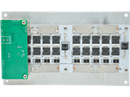
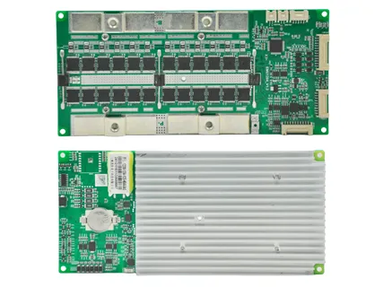
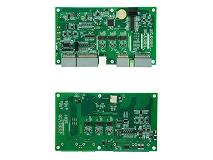
For C&I energy storage integrators and battery manufacturers, ENJIE currently offers a modular high-voltage platform consisting of BCU, BMU, and high-voltage control hardware.
The EHVS500 series is designed for 100V–800V, 50A/100A/150A series-connected LFP or NCM battery systems. ENJIE's platform also provides high-precision voltage/current monitoring, CAN/RS485/Ethernet communication, SOC/SOH management, automatic BMU addressing, relay control, data storage, and passive cell balancing.
For OEM projects, the more useful approach is to provide the battery configuration, PCS model, system power, target energy capacity, communication protocol, and expansion requirements first. The BMS high voltage architecture can then be matched to the complete ESS rather than selected as an isolated component.
Selecting a high voltage battery management system for commercial and industrial energy storage requires more than matching a voltage and current rating.
The correct high voltage BMS must coordinate cell-level monitoring, SOC/SOH estimation, balancing, insulation protection, contactor and precharge control, PCS communication, EMS integration, and fault management across the complete battery cluster.
For C&I projects, the most reliable selection process starts with the battery and PCS architecture. Once voltage range, current, series configuration, communication protocol, cluster quantity, and operating environment are defined, the appropriate HV BMS architecture becomes much easier to determine.
There is no single universal threshold for every application. In C&I battery energy storage, high-voltage systems commonly operate at several hundred volts DC. ENJIE's current high-voltage ESS platform covers systems from 100V to 800V.
A typical system includes BMUs for cell monitoring, a BCU for battery-cluster management, and high-voltage control hardware for current measurement, contactors, precharge, and protection.
The BMS normally provides the PCS with battery status, SOC, alarms, and permissible charge/discharge limits. The PCS controls power conversion according to its own control logic and the limits received from the battery system.
Provide battery chemistry, cell model, series count, minimum/maximum voltage, current, PCS power and model, communication protocol, battery-module quantity, cluster configuration, operating environment, certification requirements, and expected production volume. This allows the supplier to evaluate the complete system rather than recommending a BMS from voltage alone.