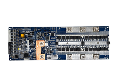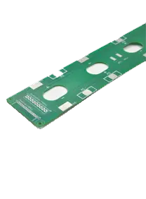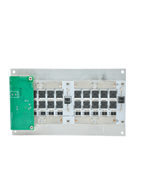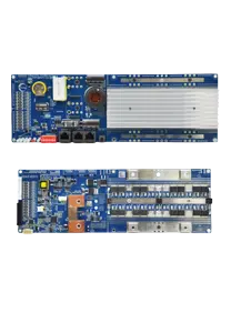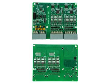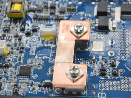
Battery management system development does not always end when the main BMS motherboard is finalized. Different battery PACK projects may require additional communication ports, status indicators, display connections, switches, signal conversion, cell acquisition interfaces, or other functions that were not included in the original motherboard design.
Redesigning the complete BMS for every customer requirement can increase development cost, validation work, production complexity, and maintenance risk. Separate functional boards provide a more flexible way to adapt a stable BMS platform to different battery configurations, enclosures, external devices, and application requirements.
The terms expansion board, adapter board, indicator board, acquisition board, and add-on board are sometimes used interchangeably. However, they do not always describe the same function. Understanding these differences helps battery manufacturers specify the correct board instead of selecting an accessory only by its connector layout or product name.
An expansion board is an additional circuit board used to extend the functions or interfaces of a primary BMS. It connects to the main BMS motherboard and adds capabilities that are not available, or are not conveniently accessible, on the original board.
Depending on the system design, an expansion board may add:
CAN or RS485 communication interfaces;
Internal parallel communication ports;
LCD or touch-screen connectivity;
Bluetooth or Wi-Fi functions;
SOC indicator LEDs;
Reset or power switches;
Address-setting switches;
External alarm outputs;
Relay control interfaces;
Cell voltage and temperature acquisition;
Active balancing interfaces;
Additional input and output channels.
The main purpose is to expand the BMS without significantly modifying its validated motherboard hardware.
ENJIE describes its expansion-board category as a group of customized functional boards for specific application scenarios. The category currently includes adapter and indicator boards, acquisition boards, and display screens. ENJIE also states that these boards can reduce repeated motherboard modifications and help maintain the stability of the core BMS design.
A separate board can be useful when a BMS platform is already stable but a new project requires a different external interface or accessory.
For example, one battery PACK may need only basic CAN communication, while another project using the same BMS motherboard may require:
CAN and RS485 ports;
Six SOC indicator lights;
An external reset button;
Address selection for parallel PACKs;
A local display;
An additional communication interface.
Instead of redesigning and revalidating the main BMS for each configuration, the manufacturer can develop a project-specific expansion board.
This modular approach can offer several benefits:
Reduced motherboard changes
The validated core circuit can remain unchanged.
Faster project adaptation
New interfaces can be added through a smaller accessory board.
Simpler maintenance
A damaged or outdated accessory board may be replaced without replacing the main BMS.
Flexible PACK layout
External connectors can be positioned where they are easier to install and access.
Product platform standardization
One BMS motherboard can support several battery products through different expansion configurations.
The actual advantages depend on interface compatibility, firmware support, electrical design, installation space, and validation requirements.
An adapter board is primarily used to connect two components that cannot be connected directly because they use different connectors, pin definitions, physical layouts, or signal interfaces.
ENJIE describes adapter boards as interface converters that transfer the signal of one interface to another so that otherwise incompatible devices can communicate or interact. The boards may also provide signal transmission, power connections, switches, communication ports, and status indicators.
A basic adapter board may perform one or more of the following functions:
Change one connector type to another;
Rearrange the connector pin sequence;
Move motherboard interfaces to a more accessible location;
Route communication signals to external equipment;
Distribute auxiliary power;
Integrate a reset or on/off switch;
Provide CAN or RS485 connectors;
Add address-selection switches;
Add visible status indicators;
Connect the BMS to a project-specific cable harness.
The board normally receives signals through one interface and routes them to another interface according to a defined circuit and pin mapping.
Not necessarily.
An adapter board may physically route CAN signals from one connector to another without changing the CAN protocol. It may adapt:
Connector shape;
Pin sequence;
Cable direction;
Installation position;
Signal access point.
This is different from converting CAN communication into RS485 communication. True protocol conversion generally requires suitable transceiver hardware, processing logic, firmware, and message mapping.
Therefore, the phrase “interface conversion” can refer to different technical functions:
| Conversion type | Typical function |
|---|---|
| Mechanical conversion | Changes connector style or physical layout |
| Pinout conversion | Rearranges signal positions between connectors |
| Voltage-level conversion | Changes signal voltage when designed to do so |
| Communication-interface conversion | Converts one electrical interface to another |
| Protocol conversion | Translates data formats or communication protocols |
| Signal distribution | Routes one interface to several external ports |
Buyers should confirm which type of conversion is actually supported. An adapter board with a CAN connector does not automatically translate the inverter protocol or make two devices compatible.
ENJIE’s LED010-V2.0 is described as an interface expansion board that transfers external interfaces from the BMS motherboard to facilitate flexible installation. Its listed functions include:
Six SOC indicators;
An 8-bit address DIP switch;
One reset switch;
One CAN/RS485 interface for inverter communication;
Two internal RS485 parallel communication interfaces.
The listed dimensions are 135 mm × 28 mm.
This example shows that one board can perform both adaptation and expansion functions. It relocates or transfers interfaces while also integrating indicators, switches, and communication connections.
The difference between an expansion board and an adapter board is mainly their primary design purpose.
An expansion board is intended to add or extend functions. An adapter board is primarily intended to connect, convert, relocate, or reorganize interfaces.
However, these categories can overlap. An adapter board may add indicators or switches, while an expansion board may include connector adaptation. In practical BMS projects, the board should be classified according to what it actually does rather than its marketing name.
| Comparison | Expansion Board | Adapter Board |
|---|---|---|
| Primary purpose | Add or extend BMS functions | Connect or adapt different interfaces |
| Typical role | Functional expansion | Interface conversion or relocation |
| Common functions | Display, communication, Wi-Fi, Bluetooth, I/O or monitoring | Connector adaptation, pin routing, signal transfer and external port access |
| Does it add new functions? | Usually | Sometimes, but not always |
| Does it change the main BMS? | Usually avoids motherboard changes | Usually avoids motherboard changes |
| Typical connection | Plugs into an expansion interface | Installed between BMS and external device or harness |
| Firmware support | May require firmware support | May require firmware support if active functions are included |
| Customization focus | Function, interface quantity and control logic | Connector, pinout, signal type and installation layout |
| Example use | Add a display or communication module | Adapt motherboard connectors to an inverter cable |
| Design complexity | Ranges from simple to highly integrated | Ranges from passive routing to active signal conversion |
An expansion board may introduce a capability that did not previously exist on the main BMS configuration.
Examples include:
Adding an LCD interface;
Adding Bluetooth monitoring;
Providing additional communication ports;
Adding a dry-contact output;
Adding more temperature-sensor inputs;
Adding active balancing control;
Adding parallel PACK addressing.
The motherboard and firmware must already support the expansion, or the project may require software modification.
An adapter board often makes an existing BMS capability usable in a specific product.
For example, the BMS may already support CAN communication, but its onboard connector may not match the cable or enclosure used by the customer. An adapter board can transfer that CAN interface to a different connector or physical position.
In this situation, the communication function already exists. The adapter board mainly changes how the interface is accessed.
An interface board may simultaneously:
Transfer the BMS communication connector;
Add SOC indicator LEDs;
Add a reset switch;
Add address switches;
Provide several external communication ports.
Such a product can reasonably be described as both an adapter board and an expansion board.
For SEO and product classification, it is still useful to explain the distinction because buyers searching for an adapter may have a different need from buyers searching for additional BMS functionality.
An indicator board provides visual information about battery or BMS operating status. It usually includes LED lamps or other indicators controlled by the BMS.
Depending on the system design, the LEDs may represent:
Power-on status;
Charging status;
Discharging status;
SOC range;
Communication status;
Warning condition;
Protection status;
Fault condition;
PACK address or operating mode.
Different colors, positions, flashing frequencies, and lighting patterns can represent different states.
ENJIE explains that its indicator boards integrate indicator lights on the board and communicate information through defined lighting patterns. Additional features such as communication interfaces and switches may also be integrated.
An indicator board normally provides simplified status information through LEDs. A display screen can show more detailed values and menus.
| Function | Indicator Board | Display Screen |
|---|---|---|
| Basic battery status | Yes | Yes |
| Numerical voltage display | Usually no | Usually yes |
| Current display | Usually no | Usually yes |
| Temperature display | Limited or no | Usually yes |
| SOC display | LED levels or segments | Numerical or graphical |
| Alarm detail | General warning light | Specific alarm information |
| Parameter configuration | Usually no | May be supported |
| Cost and complexity | Lower | Higher |
| Space requirement | Smaller | Larger |
The correct choice depends on the amount of information the end user needs and how frequently the device will be accessed.
An acquisition board is used to collect battery cell voltage, temperature, or other monitoring signals close to the cells. It may replace part of a conventional cable-based cell sampling harness and provide a more organized connection within the battery module.
ENJIE explains that cell acquisition boards can reduce the number of individual cables inside a battery PACK, simplify assembly, and improve the internal layout. Its current ECGA and ECGB boards are designed around different cell sizes, with completed versions associated with 100Ah and 280Ah cells. Customized boards can also be developed for other cell brands, dimensions, capacities, and series configurations.
An acquisition board may include:
Cell voltage sampling connections;
Temperature sensor connections;
Connector interfaces to the BMS or BMU;
Signal-routing circuits;
Fuse or protection components;
Active balancing interfaces;
Mechanical mounting features.
An acquisition board and adapter board can both route signals, but their main roles are different.
| Comparison | Acquisition Board | Adapter Board |
|---|---|---|
| Primary role | Collect cell or module data | Adapt or transfer interfaces |
| Installation position | Near battery cells or modules | Between BMS and external component |
| Typical signals | Cell voltage and temperature | Communication, switch, display or power signals |
| Design dependence | Strongly affected by cell layout and dimensions | Strongly affected by connector and interface definitions |
| Main benefit | Reduces sampling cables and organizes cell connections | Simplifies external connection and interface compatibility |
| Customization basis | Cell size, series count and module design | Connector, pinout, device and enclosure design |
An acquisition board may also contain active balancing connections, but it should not be confused with a complete active equalizer unless the required balancing circuit is included.
Expansion, adapter, indicator, and acquisition boards support different stages of battery PACK design and integration. Although some functions may overlap, each board type addresses a different requirement involving feature expansion, interface compatibility, status display, or battery data acquisition.
An expansion board is used when a battery project requires functions beyond the standard BMS configuration, such as an LCD or touch screen, Bluetooth or Wi-Fi connectivity, additional CAN or RS485 interfaces, dry contacts, alarm outputs, PACK address settings, status LEDs, or parallel battery communication. It is particularly useful when the main BMS design is already stable and the manufacturer wants to add project-specific functions without redesigning the core motherboard.
An adapter board is suitable when the BMS and connected equipment use different connectors, pin layouts, cable arrangements, or interface positions. It can adapt a BMS connector to an inverter cable, relocate motherboard ports to an enclosure panel, connect a standard BMS to a customized wiring harness, or combine switches, indicators, and communication ports on one interface board. The design should be based on confirmed connector drawings and pin definitions for both connected devices.
An indicator board provides simple and visible battery status information without requiring a full LCD display. It can be used in residential energy storage batteries, telecom backup systems, portable power products, AGV battery PACKs, industrial backup equipment, battery cabinets, and parallel low-voltage storage systems. LED colors and flashing patterns should be clearly defined so users can distinguish normal operation, SOC levels, communication activity, alarms, and protection conditions.
An acquisition board is used to collect cell voltage and temperature signals while reducing the number of individual sampling wires inside a battery PACK. It is suitable for large-format prismatic cell modules, residential and commercial energy storage PACKs, high-voltage battery modules, compact battery assemblies, and systems requiring active balancing connections. Because cell dimensions, terminal positions, capacity, and series configurations vary, acquisition boards often require mechanical and electrical customization.
An expansion board may be appropriate when one or more of the following conditions apply:
The main BMS lacks a required external interface.
The project needs a display, indicator, Bluetooth, Wi-Fi, or additional communication function.
The motherboard is already validated and should not be redesigned.
The same BMS platform will be used in several product configurations.
The customer requires a project-specific external control interface.
Future upgrades or optional accessories are expected.
The interface needs to be serviceable or replaceable separately.
Before choosing an expansion board, confirm that the main BMS provides the hardware and firmware resources required to support it.
Adding a connector does not create a function that the BMS cannot process. For example, adding a second CAN connector does not automatically create a second independent CAN channel if the motherboard provides only one communication circuit.
An adapter board may be more appropriate when the required function already exists but cannot be connected conveniently.
Typical situations include:
The BMS and inverter use different connectors;
The customer requires a different cable orientation;
Motherboard interfaces must be moved to the enclosure panel;
Several external connections must be combined into one board;
The existing pin sequence does not match the customer harness;
Status indicators or a reset switch must be installed near the enclosure surface;
A standard BMS must fit a customized PACK structure.
The adapter board should be developed only after confirming:
BMS connector drawing;
External device connector drawing;
Signal type;
Pin definition;
Supply voltage;
Maximum current;
Communication protocol;
Grounding method;
Cable length;
Installation dimensions.
The term add-on board may broadly refer to an expansion board, adapter board, indicator board, acquisition board, communication board, or display board. Because these products perform different functions, buyers should avoid requesting an add-on board based only on a reference image or general product name. A structured selection process helps clarify technical requirements, reduce interface errors, prevent unnecessary motherboard redesign, and improve compatibility between the BMS, battery PACK, and external equipment.
The first step is to determine exactly what the board must achieve within the battery management system. A project may need additional CAN or RS485 communication, a relocated interface, connector conversion, SOC indicator lights, a reset switch, PACK address settings, a display connection, cell voltage and temperature acquisition, active balancing connections, or auxiliary power distribution.
These requirements should be described in a written functional specification. A clear description of the required inputs, outputs, interfaces, and operating logic is more useful than selecting a board based only on its physical appearance. It also allows the supplier to determine whether the project requires an expansion board, adapter board, acquisition board, indicator board, or a customized combination of several functions.
The add-on board must be matched to the exact BMS platform used in the battery system. Buyers should provide the BMS model, hardware version, firmware version, connector type, pin definition, and available expansion interfaces.
Boards developed for one BMS series may not work with another model, even when the connector shape and number of pins appear similar. Differences in signal voltage, communication channels, power supply, grounding, firmware logic, or pin arrangement may create incompatibility. Confirming the complete BMS version helps prevent incorrect connections and ensures that the main controller can recognize and operate the additional board functions.
Every device connected to the add-on board should be identified before the hardware design is finalized. This may include an inverter, charger, LCD, external switch, parallel battery controller, alarm lamp, current sensor, BMU, BCU, or cell sampling harness.
For each connected device, buyers should provide the exact model, connector specification, interface type, pin definition, supply requirements, and communication protocol. This information allows the supplier to confirm whether the board only needs to route existing signals or must include additional conversion, power supply, protection, or control circuits.
Each connection should be classified according to its electrical function. Signals may operate as inputs, outputs, bidirectional communication channels, power supplies, grounds, dry contacts, analog measurements, or digital controls.
The board must support the correct voltage, current, polarity, and signal direction for every interface. For example, a 12V control signal should not be connected directly to a 5V logic input unless the board includes a suitable voltage conversion or protection circuit. The same principle applies to communication transceivers, relay outputs, sensor inputs, display power supplies, and auxiliary interfaces. Confirming these parameters prevents damage to the BMS and connected devices.
For CAN, RS485, or other communication interfaces, the electrical connection and software protocol must both be confirmed. Buyers should provide the baud rate, message protocol, CAN ID or device address, termination requirements, pin definition, ground reference, connector specification, and required cable length.
An interface board cannot resolve incompatible communication protocols simply by changing the connector. Protocol conversion requires appropriate transceiver circuits, a processor, firmware, and specifically developed message mapping. When the board only routes an existing CAN or RS485 channel, the BMS and external device must already use compatible communication logic.
When an indicator board is required, the number of LEDs, LED colors, displayed status, flashing patterns, and SOC indication method should be clearly defined. Buyers should also specify how warning conditions, protection events, communication faults, and normal operating states should appear to the user.
The functions of reset switches, power switches, and address DIP switches must also be confirmed. The hardware configuration and indicator behavior should match the BMS firmware. Adding an LED or switch to the circuit does not guarantee that the BMS can control or interpret it unless the corresponding software logic is available.
Mechanical compatibility is especially important for adapter boards, indicator boards, and acquisition boards because they often interact directly with the battery enclosure, cable layout, or cell arrangement. Buyers should provide the required PCB dimensions, mounting-hole positions, maximum component height, connector orientation, enclosure opening dimensions, cable exit direction, electrical clearance, and installation method.
The board should fit the available space without creating cable stress, connector interference, insufficient insulation distance, or maintenance difficulties. Vibration conditions should also be considered when selecting mounting methods, connector locks, component placement, and PCB support structures.
The operating environment affects the selection of PCB materials, protective coating, connectors, components, mounting methods, and testing procedures. The board may need to operate under high or low temperatures, high humidity, dust, condensation, vibration, mechanical shock, salt spray, or industrial electromagnetic interference.
These conditions should be communicated before development begins. For example, a board used inside a stationary indoor energy storage cabinet may require a different design from one installed in a vehicle, outdoor enclosure, coastal environment, or industrial site with strong electromagnetic noise. Environmental requirements can influence conformal coating, connector sealing, component temperature ratings, grounding, shielding, and vibration resistance.
Before mass production, buyers should define the prototype quantity, expected annual production volume, sample approval process, and required validation tests. Testing may include functional verification, continuity testing, communication testing, indicator testing, power-on testing, environmental testing, and firmware compatibility validation.
Traceability requirements should also be confirmed, including board labels, serial numbers, production records, firmware versions, and inspection reports. Although an add-on board may be smaller and less complex than the main BMS, incorrect pin mapping, unstable communication, insufficient electrical protection, or incompatible control logic can still create significant system risks. A controlled prototype and validation process should therefore be completed before the board enters volume production.
“Expansion board,” “adapter board,” and “interface board” are broad terms. Two suppliers may use the same term for different functions.
The technical specification should describe what signals enter the board, what signals leave it, and what processing occurs between them.
Two 8-pin connectors can have completely different pin definitions, signal voltages, and functions.
Compatibility requires confirmed connector and pinout drawings.
A passive routing board cannot translate one communication protocol into another. Protocol translation requires suitable hardware and firmware.
An expansion board may include switches, displays, or communication ports that the BMS firmware must recognize.
Hardware connection alone does not guarantee functional compatibility.
Cell voltage acquisition signals require accurate routing and protection. They should not be combined casually with communication or auxiliary power circuits.
If one adapter board supplies power to several external devices, the upstream connector, cable, PCB trace, and protection circuit must support their combined current.
Wiring diagrams, service manuals, cable labels, test procedures, and software configuration should be updated when an interface board changes.
Battery manufacturers should provide the following information before requesting a quotation.
Battery manufacturers should provide the following information before requesting a quotation.
| Information Category | Details to Provide |
|---|---|
| Core BMS Information | BMS modelHardware versionFirmware versionInterface drawingConnector modelPin definitionAvailable expansion functions |
| Functional Requirements | Required board typeRequired communication interfacesRequired indicatorsRequired switchesRequired acquisition channelsRequired power outputsRequired balancing interfaces |
| External Device Information | Device name and modelConnector drawingPinoutSupply voltageMaximum currentCommunication protocolCommunication mapping |
| Mechanical Information | PCB dimensionsMounting-hole positionsConnector position and orientationMaximum component heightEnclosure layoutCable directionCell dimensions, where applicable |
| Environmental Information | Operating temperatureStorage temperatureHumidity rangeVibration conditionsDust and moisture exposureRequired protective coatingElectromagnetic environment |
| Production Requirements | Prototype quantityExpected production volumeTesting requirementsCertification requirementsLabeling requirementsTraceability requirementsPackaging requirements |
It can be. In a broad product classification, an adapter board may be included under expansion accessories because it extends how the BMS connects to other equipment. Functionally, however, its primary purpose is usually interface adaptation rather than adding a completely new BMS capability.
No. An expansion board normally works with the main BMS and depends on its power supply, communication, control logic, or firmware. It does not replace the core battery protection and management functions.
Only when it includes the required CAN and RS485 transceivers, processing hardware, firmware, and protocol mapping. A passive connector-routing board cannot perform protocol conversion.
An indicator board usually communicates basic status through LEDs. A display screen can present detailed values such as voltage, current, temperature, SOC, SOH, alarms, and settings when supported by the BMS.
Both can connect cells and temperature sensors to the BMS. A sampling cable uses individual wires and connectors, while an acquisition board organizes the sampling connections on a PCB close to the cells. The board may reduce wiring complexity but usually requires customization for the battery module layout.
Only when the electrical interfaces, connectors, pin definitions, communication, firmware, power requirements, and control logic are compatible. Compatibility should be confirmed by the supplier.
Yes. Connector types, pinouts, communication ports, indicator LEDs, switches, address settings, dimensions, and mounting layouts can be customized when supported by the BMS platform and validated for the project.
An acquisition board or compatible sampling harness is normally used for cell voltage and temperature collection. The choice depends on cell dimensions, series count, PACK structure, assembly method, maintenance requirements, and BMS interface.
Expansion boards and adapter boards support different but sometimes overlapping functions in a battery management system. An expansion board primarily adds capabilities such as displays, communication ports, indicators, control interfaces, or monitoring functions. An adapter board primarily connects, relocates, or converts interfaces so the BMS can work with a specific cable, enclosure, inverter, or external device.
Indicator boards provide visible battery status, while acquisition boards collect cell voltage and temperature signals close to the battery cells. In some products, several of these functions are integrated onto one circuit board.
The correct selection should be based on the required function, BMS model, connected equipment, pin definition, electrical level, communication protocol, mechanical layout, firmware support, and operating environment. Providing complete interface drawings and system requirements allows the add-on board to be developed as part of the complete BMS architecture rather than as an isolated connector accessory.