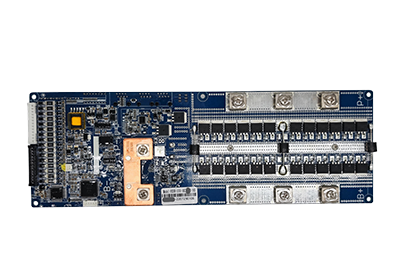
Selecting cable size for a battery management system is not as simple as choosing one wire gauge for every connection. A BMS uses several cable types to measure cell voltage and temperature, communicate with an inverter or controller, connect external switches and displays, and control auxiliary components. Each cable performs a different electrical function and therefore has different sizing priorities.
A cell voltage sensing wire normally carries very little current, while a communication cable must maintain signal integrity across the required distance. A relay or auxiliary power cable may need to carry more current than either of them. Using an unnecessarily large conductor can increase connector size, harness stiffness, weight, and assembly cost, while using an unsuitable small conductor may increase resistance, voltage drop, heating, mechanical weakness, or signal instability.
The correct selection must account for cable function, current, length, connector limitations, installation environment, routing, insulation, communication protocol, and the requirements of the BMS manufacturer. This guide explains how to evaluate sensing and communication wires without confusing them with the high-current battery cables used in the main charge and discharge circuit.
The first step in selecting bms cable size is identifying what the cable is expected to do. Two wires connected to the same BMS may require different conductor sizes because they carry different signals, currents, and levels of electrical risk.
BMS cables can generally be divided into the following functional categories:
| Cable type | Main function | Main sizing considerations |
|---|---|---|
| Cell voltage sensing cable | Measures individual cell or cell-group voltage | Measurement accuracy, connector size, wire resistance, length and mechanical strength |
| Temperature sensor cable | Connects NTC or other temperature sensors | Sensor accuracy, routing, insulation and connector compatibility |
| CAN communication cable | Transfers differential communication data | Twisted-pair construction, impedance, shielding, length and termination |
| RS485 communication cable | Transfers differential serial data | Pair balance, shielding, grounding, routing and communication distance |
| Switch cable | Connects an on/off, reset or wake-up switch | Control current, voltage, length and switch logic |
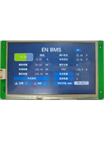
| LCD cable | Connects a compatible BMS display | Supply current, communication interface, connector pinout and cable length |
| Relay control cable | Controls contactors or pre-charge relays | Coil current, voltage drop, output rating and transient protection |
| Auxiliary power cable | Supplies a BMS or external accessory | Continuous current, startup current, voltage drop and temperature |
| Current sensor cable | Connects a shunt or Hall-effect sensor | Signal type, shielding, grounding and measurement accuracy |
| Main battery cable | Carries charge and discharge current | Ampacity, voltage drop, thermal rise, insulation and fault-current capability |
The main battery cable should not be sized according to the same criteria as a cell sensing or communication harness. Main power cables can carry tens or hundreds of amperes, whereas many sensing wires carry only measurement signals.
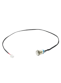
ENJIE currently lists standard sampling, switch, and LCD cables for its BMS products. Published examples include an EJ-A-13P 750 mm sampling cable, an XHB2P-400 mm on/off cable, and a 5P LCD003/004 display cable. These standard examples use AWG24 UL1007 wire, but ENJIE also states that plug type, wire type, conductor diameter, and length can be customized according to project requirements.
This does not mean AWG24 is automatically suitable for every BMS connection. It only shows that one conductor specification may be appropriate for specific low-current cables when the connector, length, electrical function, and product design have been verified together.
A cell voltage sensing harness connects the BMS measurement inputs to electrical points across a series-connected battery string. The BMS uses these wires to determine the voltage of each cell or parallel cell group.
Because the measurement inputs normally draw very little current, ampacity is not usually the primary sizing factor. Instead, designers should evaluate:
Wire resistance;
Harness length;
Connector and terminal dimensions;
Measurement accuracy;
Mechanical strength;
Flexibility;
Insulation rating;
Temperature rating;
Vibration resistance;
Assembly method.
A sensing wire has electrical resistance determined by its conductor material, cross-sectional area, and length. Although the BMS input current is normally low, excessive resistance or inconsistent connections can still affect measurement stability, fault detection, and diagnostic performance.
The resistance of the sensing path includes more than the wire itself. It may also include:
Crimp terminals;
Connector contacts;
Welded or bolted cell connections;
PCB traces;
Fuses or protective resistors;
Intermediate plugs;
Adapter or acquisition boards.
A larger conductor generally has lower resistance, but choosing the largest possible wire is not automatically beneficial. A large wire may be too stiff for a compact battery module and may not fit the specified connector terminal.
The conductor should therefore be selected within the range supported by the connector and BMS manufacturer while maintaining acceptable resistance and mechanical reliability.
Longer sensing wires have higher resistance and provide a larger path for electromagnetic interference. They also increase harness weight and make routing more difficult.
Battery PACK designers should position the BMS or acquisition board so sensing wires can reach the cells without unnecessary loops or excessive slack. When long sampling distances cannot be avoided, the design team should confirm:
Maximum permitted harness length;
Voltage measurement accuracy;
Noise-filtering requirements;
Connector quantity;
Fuse or resistor placement;
Harness routing;
Whether a distributed acquisition board is more suitable.
In a large battery system, placing local cell monitoring boards near the cells can reduce the length of individual sensing connections.
Every connector terminal supports a defined conductor range. A wire that is too small may not crimp securely, while a wire that is too large may damage the terminal or fail to enter the connector housing.
The selected wire must be compatible with:
Terminal crimp range;
Insulation diameter;
Connector cavity size;
Required pull force;
Crimping equipment;
Inspection method.
A conductor should never be changed without checking whether the original terminal and crimp tooling still meet the required mechanical and electrical specifications.
Even when a very thin conductor could carry the sensing current electrically, it may not provide enough mechanical strength for battery assembly, transportation, maintenance, or vibration.
The harness may experience:
Pulling during assembly;
Repeated bending;
Connector insertion and removal;
Vibration;
Abrasion against enclosure edges;
Thermal expansion and contraction.
Strain relief, protective sleeving, cable clips, grommets, and suitable bend radii may be as important as conductor size.
Temperature sensor cables commonly connect NTC thermistors to the BMS. The BMS determines temperature by measuring an electrical characteristic of the sensor, usually resistance.
These wires carry a low-level measurement signal, so selection should focus on:
Sensor accuracy;
Resistance consistency;
Cable length;
Connector reliability;
Operating temperature;
Routing near heat sources;
Mechanical protection.
A temperature sensor cable should not be routed in a way that causes the sensor to measure cable heat, busbar heat, or airflow instead of the intended cell or component temperature.
The installation should clearly define whether the sensor is intended to monitor:
Cell surface temperature;
Module temperature;
Ambient temperature;
MOSFET temperature;
Contactor temperature;
Busbar temperature;
Enclosure temperature.
For long sensor cables, the designer should confirm whether wire resistance affects the temperature calculation and whether compensation is required by the BMS design.
The insulation should also tolerate the highest expected local temperature. A cable passing near a busbar, relay, heating pad, or power resistor may experience a higher temperature than the battery enclosure’s average ambient condition.
A BMS communication cable carries digital information between the BMS and devices such as an inverter, charger, energy management system, display, upper computer, or another BMS.
Communication reliability depends less on basic ampacity and more on the electrical characteristics of the signal path.
The selection process should confirm:
Communication interface;
Cable length;
Baud rate or data rate;
Connector and pinout;
Twisted-pair requirement;
Characteristic impedance where applicable;
Shielding requirement;
Termination resistance;
Grounding method;
Electrical noise environment.
CAN communication normally uses two differential conductors identified as CAN-H and CAN-L. A twisted pair helps both conductors experience similar external interference so the receiver can reject common-mode noise.
Depending on the system design, the cable may also include:
Signal ground;
Shield;
Low-voltage power;
Wake-up signal;
Additional CAN channel.
The correct conductor size should fit the connector, provide sufficient mechanical strength, and maintain reliable signal transmission over the required distance. Increasing conductor diameter alone will not correct an unsuitable cable topology, missing termination resistance, incorrect grounding, or incompatible communication protocol.
CAN networks should also be checked for:
Bus topology;
Stub length;
Termination at the correct endpoints;
Total network length;
Number of nodes;
Device address configuration.
RS485 also uses differential signaling and commonly connects through an A/B pair. Like CAN, it benefits from balanced conductors and appropriate twisting.
The system designer should verify:
A and B polarity;
Signal ground requirements;
Shield grounding;
Termination;
Biasing;
Network topology;
Maximum cable distance;
Communication address;
Baud rate.
A communication failure after replacing a cable does not necessarily mean the conductor is too small. It may be caused by reversed polarity, incorrect pin mapping, missing termination, incompatible message mapping, poor grounding, or excessive stubs.
Some advanced BMS systems may use Ethernet or other communication interfaces. ENJIE’s published high voltage bms architecture supports CAN, RS485, and Ethernet communication at the BCU level. The platform also uses CAN communication between control and acquisition components.
Ethernet connections should use the cable category, connector, shielding, grounding, and routing specified by the equipment manufacturer. A generic multi-core BMS harness should not automatically be substituted for a defined Ethernet cable.
Switch and LCD cables are generally low-current connections, but the required conductor still depends on their exact function.
A switch cable may carry a wake-up, reset, enable, or on/off control signal. Selection considerations include:
Switch voltage;
Control current;
Cable length;
Input logic;
Momentary or maintained operation;
Connector type;
Environmental exposure.
The cable normally does not carry the battery’s main charge or discharge current. Increasing its conductor size does not increase the power capability of the BMS.
An LCD cable may carry both communication signals and low-voltage power for the display. The designer must confirm:
Display supply voltage;
Maximum operating current;
Startup or backlight current;
Communication interface;
Cable length;
Connector pinout;
Permitted voltage drop.
A display that resets, flickers, or loses communication may be affected by supply voltage drop, loose contacts, electrical noise, incompatible communication, or incorrect pin mapping.
Relay control cables require more attention to current and voltage drop because a contactor coil may draw more current than a sensing or communication circuit.
The cable must be selected according to:
Coil voltage;
Continuous and pickup current;
Cable length;
BMS output rating;
Connector current rating;
Ambient temperature;
Duty cycle;
Transient suppression method.
If voltage drop prevents the contactor coil from receiving sufficient voltage, the contactor may fail to close reliably or may chatter. The control cable, connector, BMS driver circuit, and suppression component should be evaluated as one circuit.
Voltage drop becomes more important as current or cable length increases. For a conductor carrying current, the voltage drop is determined by the current and total path resistance.
For a simple two-wire power connection, both outgoing and return conductors contribute to the circuit length. Designers should therefore calculate the complete current path rather than using only the one-way distance.
Voltage drop may affect:
LCD supply stability;
Relay coil operation;
Auxiliary sensor power;
External communication modules;
BMS power inputs;
Indicator boards;
Cooling fans or low-power accessories.
Cell voltage sensing wires typically carry very little current, so their voltage-drop behavior differs from that of a powered accessory cable. However, connection resistance, wire faults, and inconsistent harness construction can still affect measurement quality.
When cable length changes, the designer should recheck:
Total resistance;
Permitted voltage drop;
Connector voltage drop;
Current demand;
Temperature rise;
Signal quality;
Short-circuit protection.
Using a larger conductor may reduce voltage drop, but it does not solve poor terminals, undersized connector contacts, unsuitable PCB traces, or loose crimp connections.
Signal integrity is a major consideration for cell sensing, temperature measurement, CAN, RS485, and current-sensor cables.
Battery PACKs can contain several sources of electrical noise:
High-current charge and discharge cables;
Contactors;
DC-DC converters;
Inverters;
Motors;
Switching power supplies;
Cooling fans;
Pre-charge circuits;
Heating systems.
Sensitive BMS cables should be routed away from noisy power conductors where practical. When signal and power cables must cross, crossing at an angle may be preferable to running them in parallel over a long distance.
Other possible measures include:
Twisted signal pairs;
Shielded cables;
Correct shield termination;
Differential communication;
Shorter cable runs;
Separate cable channels;
Ferrite components where validated;
Software filtering;
Proper grounding;
Symmetrical routing.
Cable shielding should not be applied without a grounding plan. Incorrect shield connection can create ground loops or fail to provide the intended noise protection.
For cell voltage sampling, the routing of the complete harness should be reviewed together with the BMS input filtering and battery module layout.
Cable current capacity and insulation life are affected by temperature. A wire installed inside a warm, enclosed battery PACK may not perform the same way as a wire tested in open air at room temperature.
The cable specification should account for:
Maximum ambient temperature;
Local hot spots;
Cable bundling;
Enclosure ventilation;
Continuous current;
Insulation material;
Expected service life.
Insulation must also be appropriate for the voltage exposure of the circuit. A small conductor can still be connected to a high electrical potential within a series battery system even when it carries very little current.
In a high-voltage battery cluster, sensing cables connected to different modules may operate at different potentials relative to chassis ground. The system must maintain suitable creepage, clearance, isolation, connector construction, and cable insulation.
The term “low-current sensing wire” should not be interpreted as “low-voltage wire” in every part of a high-voltage battery system.
Increasing conductor size cannot compensate for poor harness manufacturing. Many cable-related problems occur at the terminal or connector rather than along the conductor.
Important quality factors include:
Correct wire stripping length;
Proper conductor crimp;
Proper insulation crimp;
Terminal insertion depth;
Connector locking;
Pull-force verification;
Contact resistance;
Pin-sequence inspection;
Continuity testing;
Short-circuit testing;
Label accuracy.
Crimping should use suitable terminals and validated tooling. Hand-soldering a wire into a terminal intended for crimping may reduce flexibility, create stress concentration, or affect connector insertion.
For cell sensing cables, 100% pin-sequence and continuity inspection can help prevent wiring errors before the harness is installed in a battery PACK.
Where vibration is expected, connector locks, secondary locks, strain relief, sleeving, clamps, and abrasion protection should be considered.
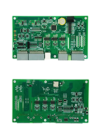
A BMS may connect to external devices through an interface, indicator, or conversion board rather than through the motherboard directly.
ENJIE describes adapter boards as interface conversion components that can support signal transfer, data transmission, power supply, communication ports, switches, and status indicators.
When an adapter board is used, cable selection must consider both sides of the board:
BMS-to-adapter cable;
Adapter-to-external-device cable.
These cables may use different connectors, pin definitions, conductor sizes, or signal assignments.
The adapter board specification should identify:
Input connector;
Output connector;
Signal direction;
Supply voltage;
Maximum current;
Communication interface;
Ground definition;
Cable pinout;
Compatible BMS model;
Compatible external device.
An adapter board can simplify system integration, but it does not remove the need to verify cable size and compatibility. If the board distributes auxiliary power to multiple devices, the upstream cable may need to carry the combined current rather than the current of only one output.
Using one wire gauge for every low-current BMS connection may simplify purchasing and production, but it is not always technically or economically optimal.
A standardized wire may work when:
All connectors support the conductor size;
Current requirements are low;
Cable lengths are similar;
Temperature conditions are controlled;
Mechanical flexibility remains acceptable;
Signal requirements are satisfied.
Different wire specifications may be preferable when:
One circuit powers a display or relay;
Another circuit carries only a sensor signal;
Communication requires a twisted or shielded pair;
Cable lengths vary significantly;
Connector terminals support different conductor ranges;
High-temperature insulation is required in one area;
Flexible routing is required in another area.
Standardization should follow engineering verification rather than convenience alone.
Before requesting a BMS cable quotation, battery manufacturers and system integrators should prepare the following information.
BMS manufacturer;
BMS model;
Product version;
Connector drawing;
Pin definition;
Interface voltage;
Supported communication protocol.
Battery chemistry;
Number of cells in series;
PACK voltage;
PACK capacity;
Battery module layout;
Operating temperature;
Application environment.
Cable function;
Conductor size;
Conductor material;
Insulation type;
Insulation temperature rating;
Cable length;
Branch length;
Connector type;
Terminal type;
Pin sequence;
Wire colors;
Labels;
Sleeving;
Shielding;
Twisted-pair requirement.
Signal type;
Continuous current;
Peak current;
Supply voltage;
Permitted voltage drop;
Communication interface;
Communication distance;
Termination requirements;
Grounding requirements.
Minimum bend radius;
Required flexibility;
Vibration exposure;
Pull-force requirement;
Connector locking;
Strain relief;
Abrasion protection;
Installation space.
Continuity testing;
Short-circuit testing;
Pin-sequence inspection;
Contact-resistance testing;
Pull-force testing;
Label inspection;
Sample approval;
Required certifications or material declarations.
Providing a wiring drawing and cable sample is generally more reliable than ordering only by a generic cable name or AWG number.
Current is important for powered cables, but sensing and communication cables must also meet signal integrity, connector, resistance, and mechanical requirements.
An AWG number does not define insulation, conductor stranding, temperature rating, shielding, connector compatibility, or cable quality.
Main power cables and BMS sensing cables carry different currents and perform different functions. They should not be selected using one universal rule.
Voltage-drop calculations should account for the full current path, including both supply and return conductors where applicable.
A larger conductor may not fit the existing terminal, seal, or connector housing.
A thicker CAN or RS485 conductor will not correct poor termination, excessive stub length, incorrect polarity, or incompatible protocols.
Two battery PACKs may use different BMS models, connector definitions, cable lengths, currents, temperatures, and installation conditions.
A technically suitable cable can still produce unstable readings or communication errors if it is routed beside noisy high-current components without suitable protection.
The correct size depends on the BMS connector, harness length, mechanical requirements, insulation, and manufacturer specification. Thin conductors such as those in the 22–24 AWG range are commonly seen in some sensing harnesses, but this should not be treated as a universal requirement. ENJIE’s listed standard sampling cable uses AWG24 UL1007 wire.
A larger wire may reduce resistance, but it must fit the connector terminal and remain flexible enough for the battery layout. Using an oversized conductor can create crimping, routing, and connector problems.
CAN communication normally carries a low-current differential signal. Pair balance, twisting, impedance, termination, shielding, routing, and connector compatibility are generally more important than simply increasing conductor diameter.
No. BMS sensing wires carry low-current measurement signals. Battery power cables carry the main charge and discharge current and require a separate ampacity, thermal, voltage-drop, and fault-current calculation.
Possibly, but not in every case. The effect of additional length depends on cable function, current, resistance, signal type, voltage drop, and communication requirements. The complete circuit should be evaluated.
Only when its conductor construction, connector pinout, shielding, electrical characteristics, and installation meet the requirements of both interfaces. The communication hardware and protocol must also be compatible.
The supplier should receive the BMS model, connector and pin drawings, cable function, wire size, length, insulation, temperature rating, communication requirements, labels, environmental conditions, and testing requirements.
Selecting BMS cable size requires a function-based approach. Cell voltage and temperature sensing wires are chosen primarily for measurement reliability, connector compatibility, mechanical strength, insulation, and routing. CAN and RS485 cables require attention to pair construction, topology, termination, shielding, and interference. Switch, display, relay, and auxiliary power cables must also be checked for current and voltage drop.
No single conductor size is correct for every BMS connection. Battery manufacturers should evaluate the complete electrical path, including the wire, terminals, connectors, PCB interfaces, adapter boards, cable length, environmental temperature, and connected device.
For customized BMS cable development, provide the BMS model, battery configuration, interface drawings, pin definitions, electrical requirements, cable dimensions, and operating environment. This allows the harness to be designed as part of the complete battery management system rather than selected only by a generic wire gauge.