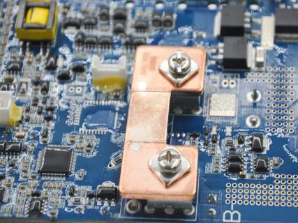
A battery management system depends on reliable electrical connections to collect cell data, communicate with external equipment, receive control inputs, and display battery status. These connections are made through several specialized cables rather than one universal BMS wiring harness.
The correct cable configuration depends on the BMS model, battery cell arrangement, connector definition, signal type, communication protocol, and external accessories. A voltage sampling harness, for example, performs a different function from an LCD cable or CAN communication cable. Using the wrong connector, pin sequence, or wire specification may result in inaccurate measurements, communication failure, or damage to the BMS.
Battery manufacturers and system integrators should therefore identify each cable by its function rather than by appearance alone. This guide explains the common names, functions, specifications, and selection considerations for BMS cables used in lithium battery PACKs.
A BMS cable is a wire or preassembled wiring harness that connects the battery management system to battery cells, temperature sensors, switches, display screens, communication devices, or other system components.
The main bms cable types can generally be divided into two functional groups:
Cables connecting the BMS to the battery PACK
Cables connecting the BMS to external interfaces and accessories
Battery-side cables collect information such as individual cell voltage and temperature. External-interface cables may connect the BMS to an on/off switch, LCD screen, inverter, charger, energy management system, or expansion board.
ENJIE currently presents three standard cable categories on its BMS cable page:
Sampling cable
Switch cable
LCD cable
Its listed products include the EJ-A-13P standard sampling cable, the XHB2P-400mm standard on/off cable, and a 5P LCD003/004 display cable. The standard examples use AWG24 UL1007 wire, although customized cable specifications can be developed according to the BMS and PACK design.
A BMS cable is normally supplied with wires and connectors assembled according to a defined pinout. The connector model, wire sequence, length, conductor size, insulation, and terminal type must match the connected BMS and device.
BMS cables should not be confused with the high-current battery power cables that connect cells, contactors, busbars, loads, and chargers. Most BMS sampling and communication cables carry low-current signals rather than the main charging or discharging current.
The cell voltage sampling cable is one of the most important wiring components in a battery management system. It is also commonly called a voltage sensing harness, cell monitoring cable, balance lead, or cell acquisition cable.
Each sensing wire connects to a defined electrical point in the series-connected battery string. This allows the BMS to calculate the voltage of each individual cell or parallel cell group.
For example, in a 16S battery PACK, the sampling harness must provide connections that allow the BMS to measure all 16 cell groups. The exact number of wires and connector pins depends on the BMS circuit and whether additional terminals are used for power supply, temperature sensors, or other functions.
Correct connection order is essential. Reversing two cell sampling wires or connecting them in the wrong sequence may produce incorrect readings and can expose the BMS input circuit to an unintended voltage.
A typical voltage sampling harness should be selected according to:
Number of cells in series
BMS connector model
Connector pin definition
Wire length
Conductor size
Insulation material
Operating temperature
Terminal and plug type
Required voltage rating
Battery PACK layout
Temperature sensor cables connect thermistors or other supported sensors to the BMS. Depending on the battery design, sensors may be placed near cells, modules, MOSFETs, contactors, busbars, or other temperature-sensitive areas.
The BMS uses temperature data to evaluate whether charging or discharging is permitted. For example, lithium battery charging may need to be restricted when cell temperature is below or above the range specified by the cell manufacturer.
Some BMS products combine cell voltage and temperature connections in one harness, while others use separate connectors. The design should follow the BMS pin definition rather than assuming that all sampling cables use the same wiring structure.
A BMS communication cable carries digital information between the battery management system and another device. Common connected devices include:
Inverters
Chargers
Energy management systems
Upper computers
LCD screens
Parallel battery controllers
Other BMS units
Diagnostic tools
Remote monitoring devices
Common communication interfaces used in battery systems include CAN and RS485. Some high-voltage or advanced energy storage systems may also support Ethernet or other project-specific communication interfaces.
The communication cable must match both the electrical interface and the communication protocol. Using the correct connector does not guarantee successful communication if the baud rate, CAN ID, message mapping, termination resistance, or software protocol is incompatible.
CAN is commonly used where multiple controllers must exchange battery status and commands. A CAN cable may carry signals such as CAN-H and CAN-L, together with ground, shielding, or power conductors where required by the design.
Cable routing, termination, shielding, and connector pinout can affect communication reliability. Long cables or electrically noisy environments may require additional attention to impedance, twisted-pair construction, grounding, and separation from high-current conductors.
RS485 is also used for communication between BMS units, displays, computers, inverters, or parallel battery systems. It normally uses a differential signal pair, often identified as A and B or RS485+ and RS485−.
As with CAN, the exact pin definition and communication mapping must be confirmed for both connected devices.
Some BMS systems distinguish between internal and external communication.
Internal communication may connect:
BMU to BCU
PACK BMS to system controller
Multiple parallel BMS units
BMS to an expansion board
External communication may connect:
BMS to inverter
BMS to EMS
BMS to charger
BMS to monitoring software
The communication cable should be labeled according to its destination and interface to reduce installation errors.
A switch cable connects an external power, reset, wake-up, or on/off switch to the BMS. This cable typically carries a low-current control signal and does not directly switch the main battery current.
Depending on the BMS design, the external switch may perform functions such as:
Turning the BMS on
Placing the BMS in standby
Waking the system from sleep
Resetting a fault
Activating or disabling an output
Reducing power consumption during storage
The switch type and operating logic must match the BMS. A momentary push button and a maintained switch do not necessarily produce the same control behavior.
An LCD cable connects the BMS to a compatible bms display screen. The screen can present information such as battery voltage, current, temperature, SOC, SOH, alarms, and protection status, depending on the BMS and display model.
ENJIE currently offers multiple display formats, including 2.7-inch, 4.3-inch, 7-inch, and round screens. Its display range includes both button-operated and touch-screen designs.
An LCD cable may carry:
Communication signals
Low-voltage power
Ground
Wake-up or control signals
Backlight or accessory signals
The display and cable must be compatible with the specific BMS model. A cable with the correct number of pins may still be unsuitable if the pin sequence, communication interface, supply voltage, or firmware protocol differs.
Additional external control cables may connect the BMS to:
Contactors
Pre-charge relays
Cooling fans
Heating devices
Buzzers
Alarm lamps
Dry-contact interfaces
Current sensors
Insulation monitoring devices
These cables should be specified according to the output type, current, voltage, and control logic supported by the BMS.
Different manufacturers may use different names for cables with similar functions. The following table provides a practical naming reference.
| BMS cable name | Alternative names | Main function |
|---|---|---|
| Cell voltage sampling cable | Voltage sensing harness, balance lead | Measures individual cell or cell-group voltage |
| Temperature sensor cable | NTC cable, thermistor harness | Connects temperature sensors to the BMS |
| Sampling harness | Cell acquisition harness | May combine voltage and temperature sampling |
| BMS communication cable | CAN cable, RS485 cable, data cable | Transfers data between BMS and external equipment |
| Parallel communication cable | Inter-BMS cable, daisy-chain cable | Connects multiple battery PACKs or BMS units |
| Switch cable | On/off cable, wake-up cable | Connects an external control switch |
| LCD cable | Display cable, screen cable | Connects the BMS to a compatible display |
| Contactor control cable | Relay harness | Sends control signals to high-voltage relays |
| Current sensor cable | Shunt cable, Hall sensor cable | Connects a current measurement device |
| Expansion cable | Accessory cable, interface cable | Connects optional BMS expansion functions |
| Power supply cable | Auxiliary power cable | Supplies low-voltage power to a BMS or accessory |
| Diagnostic cable | Programming cable, service cable | Supports commissioning, parameter setting, or firmware work |
The name printed on a drawing or product label should always be checked against the wiring diagram. Generic names such as “communication cable” or “display cable” do not provide enough information to confirm compatibility.
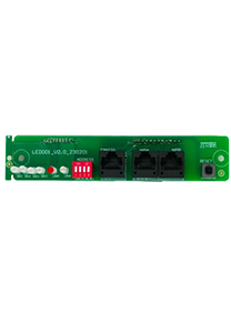
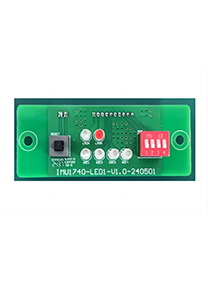
Some battery systems use an adapter or indicator board between the BMS motherboard and external cables. This arrangement can relocate connectors, convert interface definitions, add indicator lights, or provide additional communication and control ports.
ENJIE describes adapter boards as interface conversion components that can transfer signals between different interfaces. Its listed boards may also integrate indicator lights, switches, address settings, CAN, RS485, or internal parallel communication interfaces.
When an adapter board is used, buyers need to confirm two separate cable connections:
The cable between the BMS motherboard and the adapter board
The cable between the adapter board and the external device
The connector pin definitions on both sides may be different. The adapter board does not make arbitrary devices compatible unless its circuit, signal voltage, and communication definition were designed for those devices.
An adapter board can provide several practical benefits:
Moving connectors to an accessible position
Simplifying PACK assembly
Supporting different enclosure layouts
Adding indicator LEDs
Adding a reset or power switch
Providing inverter communication ports
Supporting internal parallel communication
Reducing changes to an established BMS motherboard
The cables and board should therefore be treated as one interface system during product development.
A complete BMS cable specification should include more than the cable name. At minimum, technical drawings or purchase documents should identify:
Connected BMS model
Cable function
Connector model at each end
Connector manufacturer or equivalent
Number of pins
Pin assignment
Wire sequence
Conductor size
Insulation type
Cable length
Terminal type
Operating temperature
Voltage rating
Color coding
Labeling requirements
Shielding or twisting requirements
Branch lengths
Quantity
Testing requirements
For communication cables, the specification may also need to define:
Communication interface
Twisted-pair requirement
Shield connection
Termination resistance
Grounding method
Maximum cable length
Device address
Communication direction
For voltage sampling cables, the specification should clearly identify the order of cell connections. Labels such as B0, B1, B2, B3, and B+ may be used, but the exact definition must follow the BMS documentation.
The selection process should begin with the BMS wiring diagram and interface definition.
Determine whether the cable is intended for cell sampling, temperature sensing, communication, switching, display connection, current measurement, or another function.
Cable connectors and pin definitions may differ between BMS models from the same manufacturer. Product family compatibility should not be assumed.
For an inverter communication cable, confirm the BMS-side connector and the inverter-side connector. The CAN or RS485 pin definitions must match.
Cable length should suit the PACK structure without creating excessive slack, tension, sharp bends, or difficult routing.
Conductor size, insulation, flexibility, temperature rating, shielding, and voltage rating should match the electrical function and operating environment.
Sampling and communication cables should be routed carefully around high-current busbars, power cables, contactors, motors, and switching power components that may introduce electrical noise.
Different connectors, wire colors, labels, keying features, and branch lengths can help prevent incorrect assembly.
Custom cables may be required for different plugs, cable lengths, wire diameters, connector brands, terminal arrangements, or enclosure layouts. ENJIE states that its cable assemblies can be customized according to plug type, cable type, conductor size, length, and other project needs.
Two connectors may appear similar but use different pin definitions. Compatibility must be confirmed through drawings or specifications.
An incorrect sampling sequence can cause inaccurate measurements or expose the BMS inputs to unintended voltages.
A connector does not determine whether a cable uses CAN, RS485, UART, or another interface. The electrical and software definitions must both match.
Poor routing may expose sensing and communication cables to electromagnetic interference.
Long wires can complicate PACK assembly, increase exposure to interference, and create unnecessary resistance or voltage-drop concerns in some sensing circuits.
A replacement cable should not be selected only by length, wire color, or connector pin count.
Battery systems used in vehicles, industrial equipment, or mobile applications may require connector locks, strain relief, abrasion protection, and vibration-resistant routing.
Sampling, temperature, communication, and control cables usually carry low-current signals. Their design priorities differ from those of main battery charge and discharge cables.
Before requesting a quotation, battery manufacturers and PACK integrators should provide:
BMS brand and model
Battery chemistry
Number of cells in series
Required cable function
Wiring diagram
Connector specification
Pin definition
Wire gauge
Cable length
Branch dimensions
Temperature range
Communication interface
Shielding requirement
Label and wire-color requirements
Environmental conditions
Expected production quantity
Required testing or certification
Sample or drawing for confirmation
Providing a complete interface drawing reduces the risk of producing a cable that fits mechanically but is electrically incompatible.
It is commonly called a cell voltage sampling cable, voltage sensing harness, balance lead, or cell acquisition harness. It may also include temperature sensor connections, depending on the BMS design.
No. A sampling cable carries cell-voltage or temperature signals from the battery PACK to the BMS. A communication cable transfers digital data between the BMS and another controller, inverter, display, or BMS unit.
Only when the connector, pin assignment, signal definition, wire specification, and connected functions are fully compatible. Similar appearance does not confirm compatibility.
An LCD or display cable is used. Its connector, supply voltage, communication interface, and pin definition must match both the BMS and display model.
No. Sampling wires carry measurement signals and normally use smaller conductors. Battery power cables carry the main charge and discharge current and must be sized for the system current and thermal requirements.
Yes. Cable length, conductor size, plug type, connector brand, branch layout, labels, wire colors, and other characteristics can be customized when supported by the supplier and confirmed against the system design.
BMS cables connect the battery management system to the cells, sensors, switches, displays, communication equipment, and control components required for battery operation. The main types include cell voltage sampling cables, temperature sensor cables, communication cables, switch cables, LCD cables, and external control harnesses.
Correct selection requires more than matching the connector shape. Buyers should verify cable function, connector model, pin assignment, conductor size, length, insulation, communication interface, routing conditions, and environmental requirements.
For custom battery PACK projects, supplying the BMS model, wiring diagram, connector definition, PACK layout, and connected-device specifications allows the cable assembly to be evaluated as part of the complete battery management system rather than as an isolated accessory.