Connecting multiple battery PACKs in parallel can increase the available capacity and support the expansion of an energy storage system without substantially changing its designed operating voltage. However, a parallel battery system involves more than connecting all positive terminals together and all negative terminals together.
Each PACK may have a different state of charge, internal resistance, temperature, usable capacity, and aging condition. These differences affect how current is distributed when the PACKs charge or discharge through a shared DC bus. Without coordinated monitoring and control, one PACK may carry more current than the others or experience an excessive current when it is connected.
A battery management system for a parallel architecture must therefore monitor individual PACK conditions, evaluate whether each PACK is ready to connect, coordinate charge and discharge limits, communicate with the inverter, and respond when a PACK develops an abnormal condition. The exact control method depends on whether the PACKs are directly paralleled or connected through independent DC-DC power stages.
A bms parallel connection is a battery system architecture in which multiple compatible battery PACKs operate through a shared voltage platform while being monitored and coordinated by local and system-level battery management components.
In an ideal parallel connection, the system voltage remains approximately equal to the operating voltage of one PACK, while the total ampere-hour capacity increases as compatible PACKs are added. For example, four 100V, 100Ah PACKs connected in parallel would theoretically form a 100V, 400Ah system.
This simplified calculation does not describe the complete engineering requirements. Before a PACK is connected to the common bus, the system may need to confirm:
PACK voltage
State of charge
Cell temperature
PACK temperature
Communication status
Contactor status
Insulation condition
Alarm and fault status
Available charge current
Available discharge current
A parallel BMS can use this information to determine whether the PACK should be connected, limited, placed in standby, or isolated.
ENJIE currently lists the EHVS401-24150 as a developing parallel battery PACK system based on a DC-DC architecture. Its published high-voltage BMS information states that cell voltage and temperature data from every PACK are collected and reported to the BCU.
Parallel battery systems can be designed in different ways. Two important configurations are direct parallel connection and DC-DC-based parallel connection.
In a direct parallel system, compatible battery PACKs connect to the same DC bus through contactors, fuses, and other protection components.
Once connected, the PACKs normally operate at nearly the same terminal voltage. Current sharing is influenced by the electrical characteristics of each current path, including:
PACK internal resistance
Cell resistance
Cable length and cross-sectional area
Busbar resistance
Connector resistance
Fuse resistance
Contactor resistance
Temperature
State of charge
The BMS can monitor these conditions and control contactors, but it cannot independently force every directly connected PACK to deliver exactly the same current. Careful PACK matching and current-path design are therefore important.
A DC-DC-based architecture places a controlled power-conversion stage between individual battery PACKs and the common DC bus.
Depending on the system design, the DC-DC stage can regulate how much current each PACK contributes. This gives the system more control when PACK voltages, SOC values, capacities, or electrical characteristics are not perfectly identical.
A DC-DC architecture may support:
Controlled PACK connection
Current regulation
Reduced inrush-current risk
Pack-level charge and discharge limits
Improved coordination between battery PACKs
Flexible integration of compatible PACK configurations
Isolation of an abnormal PACK
These benefits depend on the converter topology, control logic, power rating, thermal design, communication reliability, and fault-handling strategy. A DC-DC architecture should not be treated as proof that any battery PACK can be safely combined with another.
Each battery PACK in a parallel system normally requires local monitoring. Depending on the architecture, this may be performed by a BMU, a PACK-level BMS, or another cell acquisition unit.
The local monitoring unit typically collects:
Individual cell voltage
Cell or module temperature
PACK voltage
Balancing status
Sensor status
Communication condition
Local alarm information
In a high-voltage system, this data is transmitted to a central BCU or system controller. The central controller combines PACK information with system-level measurements such as DC bus voltage, total current, insulation status, relay position, and inverter requests.
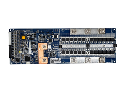
ENJIE describes its high voltage bms architecture as including BCU, BMU, and high-voltage power components. Its BMUs perform real-time cell-voltage and temperature sampling, while the BCU manages the status of the battery cluster and communicates with the inverter.
PACK-level monitoring matters because total bus voltage alone cannot show the condition of every battery. Two PACKs may have a similar terminal voltage while differing in:
Usable capacity
Cell consistency
Internal resistance
Temperature
SOC estimation
Aging condition
Available charge or discharge power
By analyzing each PACK separately, the BCU can identify an abnormal unit before it significantly affects the complete storage system.
The BCU acts as the system-level decision unit in a high-voltage parallel battery architecture. It receives data from the PACK-level monitoring units and evaluates the operating condition of the complete battery system.
In a directly connected system, the BCU may monitor individual branch currents or total system current and use contactors or operating limits to prevent a PACK from exceeding its permitted range.
In a DC-DC-based design, the controller may also send current commands or power limits to individual DC-DC modules. This can help distribute charging and discharging demand according to PACK capability.
A PACK operating at a higher temperature, lower SOC, or reduced state of health may receive a lower current limit than a healthier PACK.
The system SOC should not always be calculated as a simple average of all PACK SOC values.
If PACK capacities differ, a capacity-weighted method may be more appropriate. The control algorithm may also consider whether a PACK is connected, available, derated, or isolated.
Reliable system-level SOC calculation depends on:
Accurate current measurement
Correct PACK-capacity settings
Voltage calibration
Temperature compensation
Coulomb counting
SOC correction logic
Communication availability
Consistent firmware configuration
When additional PACKs are introduced, the system should verify their SOC and voltage before connection. Connecting a fully charged PACK directly to a significantly discharged PACK can cause a large equalization current between them.
The BCU may assign each PACK an operating state, such as:
Offline
Standby
Pre-charging
Connected
Charging
Discharging
Derated
Faulted
Isolated
This state-based control prevents the system from treating every PACK as available at all times.
Current does not necessarily divide equally simply because battery PACKs have the same nominal voltage and capacity.
A PACK with lower total resistance tends to carry more current. Its resistance includes not only the cells but also cables, contactors, fuses, connectors, and busbars. Differences in temperature and SOC can further change current distribution.
For example, two nominally identical PACKs may deliver different currents because one has:
Shorter power cables
Lower connector resistance
Newer cells
Higher temperature
Higher SOC
Lower internal resistance
Uneven current sharing can result in one PACK reaching its current, temperature, or SOC limit earlier than the others.
Engineering measures used to improve current sharing may include:
Matching battery PACK specifications and aging condition.
Using equal-length and equal-size power cables.
Designing symmetrical busbar connections.
Monitoring branch current where required.
Applying individual PACK current limits.
Using DC-DC conversion for active current regulation.
Derating PACKs according to temperature or health.
Keeping firmware and parameter settings consistent.
The appropriate method depends on system power, PACK quantity, expansion requirements, and whether direct or converter-controlled parallel connection is used.
Small SOC differences may exist during normal operation, but large differences should be addressed before directly connecting battery PACKs.
Before closing the main contactor, the BCU may compare:
Open-circuit PACK voltage
Estimated SOC
Cell-voltage range
Highest and lowest cell voltage
Temperature
Available charge and discharge limits
Fault and alarm status
If the difference is outside the permitted range, the controller may prevent connection or require a controlled pre-charge or energy-transfer process.
It is also important to distinguish between cell balancing and PACK-level balancing.
An active equalizer transfers energy among cells within a battery string to reduce cell-level voltage or SOC differences. It does not automatically solve current-sharing or SOC differences between complete battery PACKs connected to a shared bus.
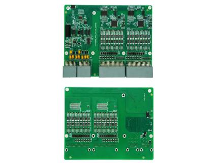
ENJIE’s active equalization board is designed to address inconsistent cell voltage during standby, charging, and discharging. The product page also identifies monitoring, wire-break detection, Bluetooth communication, data storage, and cumulative equalization-time functions.
PACK-level coordination normally requires the BCU, contactor logic, and—where applicable—DC-DC power control.
A parallel BMS must identify faults at both the cell level and the PACK level.
Possible abnormal conditions include:
Cell overvoltage
Cell undervoltage
Charge overcurrent
Discharge overcurrent
High temperature
Low charging temperature
Communication loss
Sensor failure
Contactor failure
Insulation fault
Excessive PACK-voltage difference
DC-DC converter fault
The system response depends on fault severity and architecture.
For a warning-level event, the BCU may reduce the charge or discharge limit. For a more serious event, it may command the PACK to stop operating or open the corresponding contactor.
In a properly designed parallel system, the remaining PACKs may continue supplying the load after one abnormal PACK is isolated, provided that:
The remaining capacity is sufficient
Current limits are not exceeded
The inverter accepts the revised power limits
The bus remains stable
The system control strategy permits continued operation
Not every parallel system supports uninterrupted PACK removal, hot swapping, or continued operation after a fault. These functions must be confirmed in the hardware and software design rather than assumed from the term “parallel BMS.”
The inverter or power conversion system needs accurate battery information to control charging and discharging.
The BCU normally acts as the communication gateway between the battery PACKs and the inverter. Depending on the project, communication may use CAN, RS485, Ethernet, or another defined interface.
Information transmitted to the inverter may include:
System SOC
System SOH
Total battery voltage
Total current
Maximum charge voltage
Maximum charge current
Maximum discharge current
Battery temperature
Alarm status
Fault status
Number of available PACKs
Charge enable command
Discharge enable command
The inverter may send operating commands, requested power, startup status, shutdown status, or communication heartbeats to the BCU.
If one PACK becomes unavailable, the BCU should update the system-level charge and discharge limits. This prevents the inverter from continuing to request the same power from a battery system with reduced available capacity.
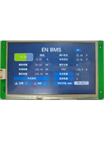
ENJIE’s published high-voltage BMS functions include CAN, RS485, and Ethernet communication, as well as SOC and SOH algorithms, current and voltage sampling, relay control, local storage, LCD expansion, and firmware-upgrade support.
A typical startup process may include the following steps, although the exact sequence varies by system design:
The BCU and PACK-level monitoring units power on.
Communication with each PACK is established.
Cell voltage and temperature data are checked.
PACK voltage and SOC differences are evaluated.
Alarm, contactor, sensor, and insulation status are verified.
The BCU confirms communication with the inverter.
A pre-charge circuit or DC-DC stage brings the bus to the required voltage.
Eligible PACKs are connected according to the control sequence.
The BCU calculates system-level charge and discharge limits.
The inverter receives permission to begin operation.
This process is intended to avoid uncontrolled connection and ensure that only qualified PACKs participate in charging or discharging.
Two PACKs marked with the same nominal voltage may still have different operating voltage, SOC, capacity, resistance, or protection parameters.
Unequal current paths can cause persistent current-sharing differences even when the battery PACKs are otherwise similar.
A total current sensor cannot always identify which PACK is carrying excessive current. Some applications require branch-current monitoring or controlled DC-DC stages.
Cell equalization reduces differences among cells inside a PACK. Parallel PACK coordination manages voltage, current, SOC, and operating status among complete battery units.
Future expansion affects communication addresses, BCU capacity, busbars, protection components, inverter limits, contactor quantity, enclosure space, and thermal design.
A BMS can only isolate a PACK if the required contactors, power architecture, sensors, and software logic are included in the system.
Battery manufacturers and ESS integrators should prepare the following information before requesting a parallel BMS configuration:
Battery chemistry
Cell model
Cells in series per PACK
PACK nominal and operating voltage
PACK capacity
Continuous and peak current
Initial number of PACKs
Maximum future PACK quantity
Direct-parallel or DC-DC architecture
Required branch-current measurement
Inverter brand and model
CAN or RS485 protocol
Contactor and pre-charge configuration
Cell-balancing requirements
Operating-temperature range
Cooling method
Enclosure and installation conditions
Certification requirements
Fault-isolation expectations
A complete system diagram is more useful than a request based only on voltage, current, or PACK quantity. It allows the BCU, local monitoring units, communication, power components, and safety logic to be evaluated together.
They may be connected only if the battery chemistry, voltage range, SOC, capacity, current capability, communication, and protection strategies are compatible. Some systems also require a system-level controller or DC-DC converter.
No. A parallel battery architecture primarily increases total ampere-hour capacity and potential current capability while maintaining approximately the same system voltage.
Each PACK generally requires independent cell and temperature monitoring. A system-level BCU may then coordinate the status and operation of all PACKs.
It may be technically possible in a specially engineered DC-DC-based system, but directly connecting dissimilar PACKs can produce uneven current distribution and operating limits. Compatibility must be evaluated before integration.
The BCU may issue an alarm, reduce system power, or isolate the affected PACK according to the configured fault strategy. The response must be defined during system design.
A system with controlled DC-DC power stages may regulate energy contribution between PACKs. A conventional cell-balancing circuit alone does not correct large SOC differences between complete battery PACKs.
A BMS parallel connection requires coordinated monitoring and control at the cell, PACK, and system levels. The BCU must understand which PACKs are available, how much current each can safely provide, whether their SOC and voltage are compatible, and how the complete battery system should communicate with the inverter.
Direct parallel systems depend heavily on PACK consistency and symmetrical power-path design. DC-DC-based systems can provide more active control over PACK current and connection, but they also add power electronics, thermal requirements, and control complexity.
For a reliable project evaluation, buyers should provide complete battery PACK specifications, current requirements, inverter communication details, expansion plans, and fault-isolation expectations. ENJIE’s EHVS401-24150 parallel battery PACK system is currently identified on the official website as under development, so its final operating parameters and customization scope should be confirmed before system integration.