Battery manufacturers and energy storage system integrators often need to decide whether multiple battery PACKs should be connected in series or in parallel. Although both configurations can support larger energy storage systems, they change different electrical characteristics and require different control strategies.
A series-connected battery system primarily increases operating voltage. A parallel-connected system primarily increases available capacity and current capability while maintaining the designed bus voltage. The BMS architecture must therefore match the way the battery PACKs are connected, monitored, protected, and coordinated with the inverter or energy management system.
Selecting the wrong architecture can create problems involving incompatible inverter voltage, uneven current sharing, complex fault isolation, insufficient system capacity, or unnecessary hardware cost. Understanding the differences between series and parallel BMS architectures helps buyers define voltage, capacity, communication, protection, and expansion requirements before starting a battery project.
A series bms manages battery modules or PACKs connected in series. In this configuration, the positive terminal of one battery module is connected to the negative terminal of the next module. The voltage of each module is added together, while the available ampere-hour capacity normally remains equal to that of one series string.
For example, connecting eight compatible 50V, 100Ah battery PACKs in series creates a nominal 400V, 100Ah battery cluster. The total energy increases because the voltage increases, but the ampere-hour rating remains 100Ah.
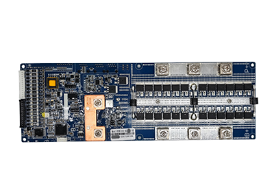
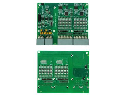
A series high-voltage BMS commonly uses a distributed or two-level architecture. BMUs installed in the battery PACKs collect individual cell voltage and temperature data. The BCU receives this information, calculates system status, communicates with the inverter, and controls the high-voltage power components.
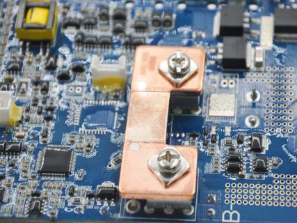
ENJIE’s EHVS500 series-connected system uses a two-level architecture consisting of a BCU, BMUs, and a high-voltage power box. Its published configuration covers a system voltage of 100V–800V and current options of 50A, 100A, and 150A.
A parallel architecture connects the positive terminals of compatible battery PACKs to a shared positive bus and the negative terminals to a shared negative bus. The total capacity increases, while the system voltage remains within the operating range of one PACK or the regulated DC bus.
The most important distinction between series and parallel battery architectures is what happens to voltage and capacity.
| Comparison | Series BMS Architecture | Parallel BMS Architecture |
|---|---|---|
| Primary purpose | Increase total system voltage | Increase total system capacity |
| System voltage | Increases as modules are added | Remains within the designed bus range |
| Ampere-hour capacity | Normally remains equal to one string | Increases as compatible PACKs are added |
| Current flow | The same current passes through the series string | Current is shared among parallel PACKs |
| Main control challenge | Monitoring many series cells and modules | Coordinating PACK status and current contribution |
| Expansion method | Add compatible modules to the series string | Add compatible PACKs to the parallel bus |
| Typical application | High-voltage ESS and high-power systems | Capacity-scalable and modular storage systems |
If four 100V, 100Ah PACKs are connected in series, the resulting cluster is approximately 400V and 100Ah. If the same four PACKs are connected in parallel, the resulting system remains approximately 100V but increases to 400Ah.
However, these simplified calculations assume that the battery PACKs are electrically compatible. Actual system design must also consider operating voltage range, allowable current, cell chemistry, SOC, internal resistance, thermal conditions, contactors, fuses, cabling, and inverter requirements.
In a series high-voltage system, the BMUs monitor individual cells and modules at different electrical potentials. Cell voltage, temperature, and balancing data are transmitted to the central BCU through an isolated communication network.
The BCU evaluates the complete battery cluster and manages:
Total cluster voltage
Charge and discharge current
Cell and PACK temperatures
State of charge
State of health
Alarm and protection status
Relay and pre-charge control
Communication with the inverter or EMS
Because the modules are connected in series, one weak or abnormal cell can restrict the operation of the complete string. If one cell reaches its upper voltage limit during charging, the system may need to reduce or stop charging even when the remaining cells have not reached the same SOC.
A parallel bms must focus more heavily on PACK-level coordination. Each PACK should be monitored independently so that the central controller can evaluate its voltage, temperature, SOC, communication status, and fault condition before allowing it to contribute power to the shared DC bus.
ENJIE currently identifies its EHVS401-24150 parallel battery PACK system as a developing product using a DC-DC architecture. The published system description states that cell voltage and temperature data from each PACK are collected and reported to the BCU.
A DC-DC-based design can provide greater control over the voltage and current contribution of individual PACKs. This is different from directly connecting battery PACK terminals without coordinated power control.
Current sharing is one of the main engineering challenges in a parallel battery system. Even when two PACKs have the same nominal voltage and capacity, differences in SOC, internal resistance, cell aging, cable resistance, temperature, or contactor characteristics can cause uneven current distribution.
A PACK with lower internal resistance may provide more current than the other PACKs. This can increase thermal stress and accelerate aging. A large voltage or SOC difference may also create an inrush or circulating current when the PACKs are connected.
A parallel BMS architecture should therefore evaluate PACK compatibility before connection and continuously monitor operating differences after connection. Depending on the system design, the control strategy may include:
PACK voltage and SOC comparison
Pre-charge or controlled connection
DC-DC current regulation
Charge and discharge limit management
Temperature-based derating
Contactor or relay isolation
Fault alarms and event recording
Inverter or EMS communication
Fault isolation is also different in series and parallel systems. Disconnecting one module from a conventional series string normally interrupts the entire current path. In a properly designed parallel system, an abnormal PACK may be isolated while compatible PACKs continue operating, provided the architecture, capacity requirements, and protection logic permit continued operation.
This potential serviceability benefit depends on the actual hardware and control strategy. It should not be assumed that every parallel battery system can automatically remove or replace a PACK during operation.
Series-connected battery modules are commonly used when the inverter requires a high DC input voltage. Raising the battery voltage allows the system to deliver the same power at a lower current.
Because electrical power is the product of voltage and current, increasing voltage can reduce the current required for a given power level. Lower current may reduce resistive losses and the conductor size required by the system, although insulation, relay, connector, and safety requirements become more demanding as voltage rises.
A high-voltage system may be suitable for:
Commercial and industrial energy storage
High-power solar-plus-storage systems
High-voltage residential storage
Factory peak-shaving systems
Microgrids
High-power backup systems
Parallel battery PACK architectures are more suitable when the main project objective is to increase energy capacity, backup duration, or current capability without changing the inverter’s voltage platform. They can also support phased capacity expansion when the system is designed to accept additional compatible PACKs.
In some projects, series and parallel connections are used together. Cells may be connected in series inside each PACK to reach the required PACK voltage, while several complete PACKs or battery strings are connected in parallel to achieve the required capacity.
These combined systems require careful coordination at the cell, PACK, string, and system levels.
The choice should begin with the inverter or power conversion system. Buyers need to confirm the required DC input voltage range before defining the number of cells and battery PACKs.
The following questions help determine the appropriate architecture:
What is the inverter’s minimum and maximum battery voltage?
What total usable energy capacity is required?
What are the continuous and peak power requirements?
How many battery PACKs will be installed initially?
Will the system require future capacity expansion?
What battery chemistry and cell configuration will be used?
What are the maximum charge and discharge currents?
How should an abnormal PACK or module be isolated?
Which CAN or RS485 protocol must communicate with the inverter?
What certifications and environmental requirements apply?
A series architecture is generally the more direct option when the project needs a higher operating voltage. A parallel architecture is generally more relevant when the voltage platform is already defined but additional capacity is required.
The selected high voltage bms must support the complete system architecture rather than only the total voltage. BMU quantity, BCU capability, current measurement, contactor control, pre-charge logic, balancing, communication, insulation, data storage, and firmware configuration should be evaluated together.
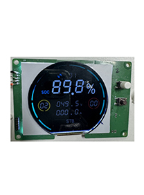
ENJIE’s high-voltage BMS platform uses BCU, BMU, and high-voltage power components to monitor and manage high-voltage battery clusters. Its published functions include CAN, RS485, and Ethernet communication, current and voltage sampling, SOC and SOH algorithms, relay control, local data storage, display expansion, and firmware upgrades.
Compatible voltage labels do not guarantee that two battery PACKs can operate safely in parallel. SOC, capacity, internal resistance, communication, protection settings, and current-sharing behavior must also be considered.
Voltage is only one parameter. The system must also be evaluated for current, cell chemistry, series count, PACK quantity, temperature sensors, contactors, balancing, and communication requirements.
New and aged PACKs, or PACKs with different capacities and internal resistance, may contribute current unevenly. The compatibility limits should be defined before system integration.
A system designed only for its initial capacity may not support additional PACKs later. Future expansion affects BCU capacity, communication addresses, current limits, busbars, protection components, enclosure space, and inverter settings.
“Series BMS” and “parallel BMS” may refer to the battery connection, the PACK architecture, or the communication structure. Buyers should provide a system diagram to avoid ambiguity during technical discussions.
They can only be connected when their voltage range, chemistry, SOC, capacity, internal resistance, communication, and protection strategies are compatible. A system-level controller or parallel management strategy may also be required.
Connecting compatible batteries in series increases voltage. The ampere-hour capacity generally remains equal to that of one battery or one series string.
No. A parallel connection normally maintains the same voltage while increasing total ampere-hour capacity and potential current capability.
Not automatically. A BMS designed only to monitor one series string may not provide PACK-level current coordination, fault isolation, addressing, or communication required by a multi-PACK parallel system.
Neither architecture is universally better. Series systems are generally selected to reach a higher inverter voltage, while parallel systems are selected to increase capacity at a defined voltage. Many large systems use a combination of both.
Series and parallel BMS architectures solve different battery system requirements. A series system increases voltage and is often selected for high-power energy storage applications. A parallel system increases capacity and can support modular expansion, but it requires careful management of PACK consistency, current sharing, SOC differences, and fault isolation.
Before selecting a BMS, battery manufacturers and ESS integrators should define the inverter voltage, required capacity, maximum current, battery chemistry, PACK configuration, communication protocol, protection strategy, and future expansion plan. Providing a complete system diagram allows the BMS architecture, BMU quantity, BCU functions, high-voltage components, and control logic to be evaluated as one coordinated solution.